
This article is the second of an ongoing series of posts documenting and describing our significant RV electrical upgrade. In our previous post, we outlined our requirements and created a schematic of a system that would meet our needs. We also discussed our desire to do the work incrementally, leaving the trailer in working order after each sub-project. Finally, we discussed our desire to build a 24 V system. In this post, we discuss a potential need for an alternative design and present its schematic. We also discuss the need to model our finished product, and we share our results.
Alternative Design
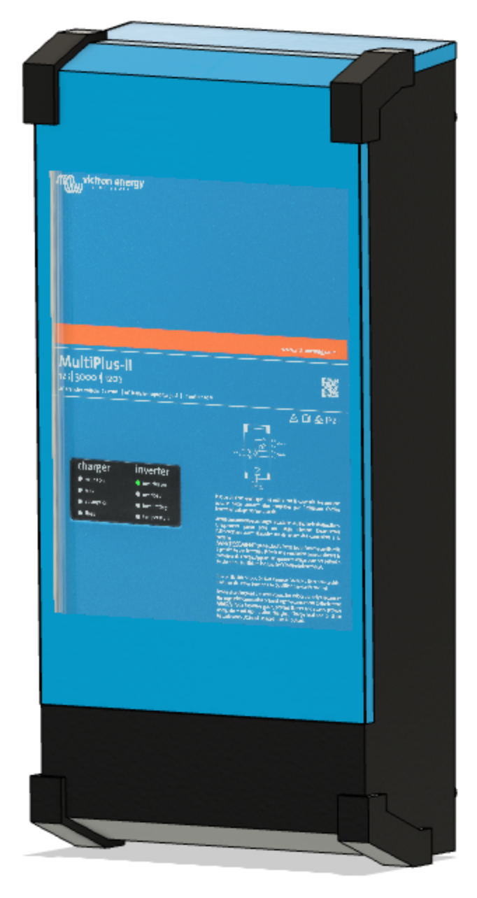
While we desire to build a 24 V system to reduce currents, Victron Energy does not currently produce a 24 V version of their MultiPlus-II 3000 VA 2x 120 V inverter/charger. However, we are hoping they announce such a device at the METS 2021 conference.
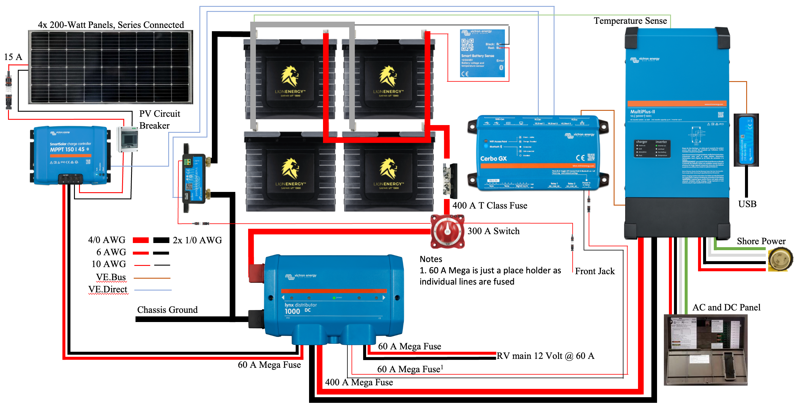
In case a suitable product does not become available, we have designed an alternative 12 V system. This version would not need a 24-12 V DC-DC converter, but increased system currents require larger wires to connect the battery bank to the inverter/charger. Figure 1 illustrates the schematic for our alternative design.
Modeling the System
Our desire to make incremental progress without wasting time or money requires us to see the outcome before taking our first steps. If we don’t know where each component will go and how it will be oriented, we will likely make mistakes that waste resources.
To visualize our project, we used Autodesk’s Fusion 360 3D modeling software to create a model of our RV’s pass-through storage space, our under-bed storage area, and the significant components of our system. Then, by placing the scale versions of the desired components into the modeled spaces, we can arrange and rearrange them to ensure the best overall final implementation. We can then undertake small projects without worrying about them negatively impacting future work. We can also simultaneously work on multiple projects that don’t interfere with one another.
RV Storage Spaces
We initially thought we would put both the power center components and the battery bank in the pass-through storage area. However, we decided to place the battery bank in the under-bed storage to reduce the temperature extremes it would otherwise experience.
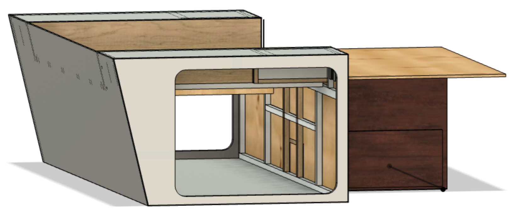
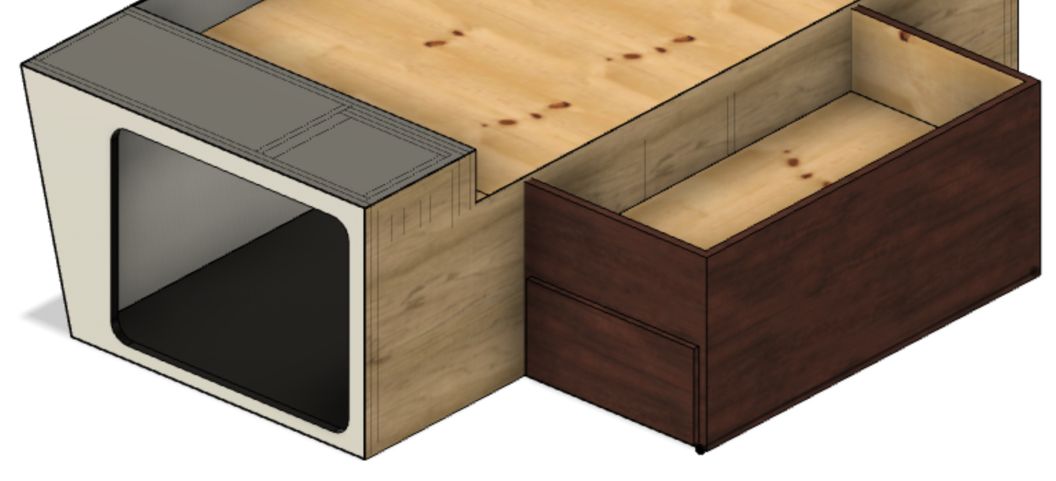
Figure 2 illustrates the pass-through and under-bed storage areas of our trailer. It might be helpful to note that the mattress sits immediately on top of these modeled objects. The under-bed storage comprises two drawers, and immediately above them, a small storage space accessible by lifting the foot of the bed. The area illustrated in Figure 3 seemed to be an ideal place for our battery bank.
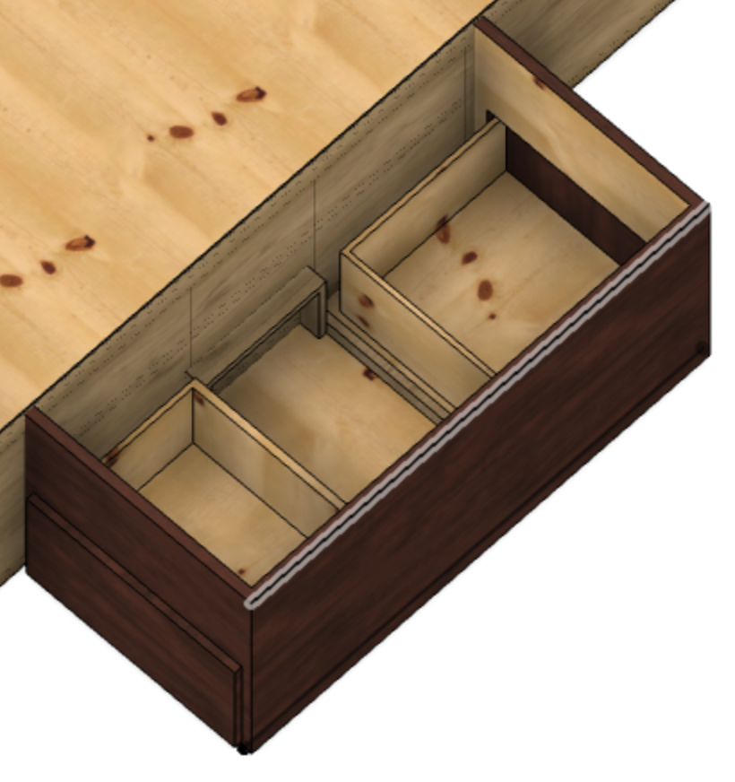
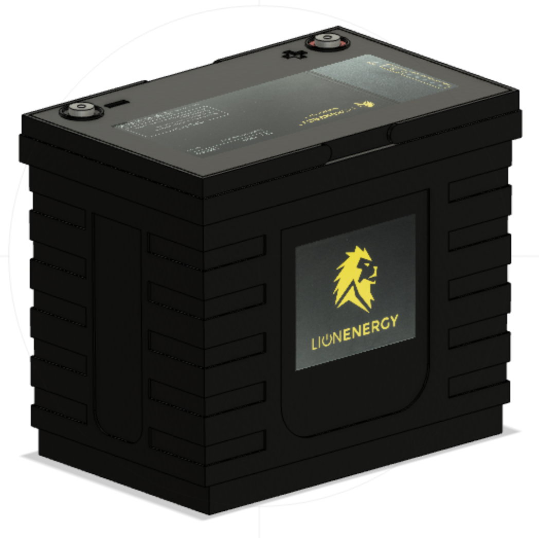
However, we discovered some completely wasted space between the two drawers during our modeling efforts, see Figure 4. This space is almost large enough for four Lion Energy UT 1200 batteries. Some modifications will be necessary, but using this space will leave both the under-bed and pass-through storage areas free for their intended purposes.
This example points out the sound practice of measuring things out and opening up places in your RV to determine what is there and what’s available. You never know when you may need a bit of space for one thing or another.
Modeled Components
Modeling the trailer spaces gave us a great reason to learn a bit about Fusion 360. While we aren’t experts, we learned enough to model each of the major components we’ll use in our system. These models are not precise, but their overall dimensions and appearance are accurate enough for our purposes.
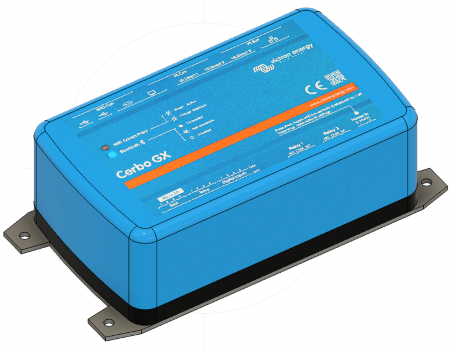
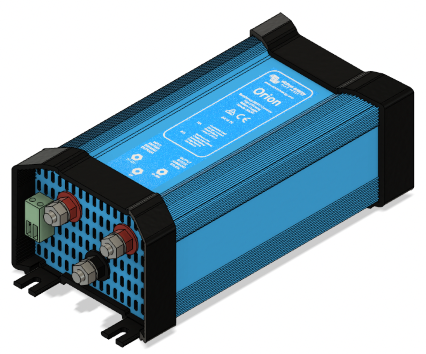
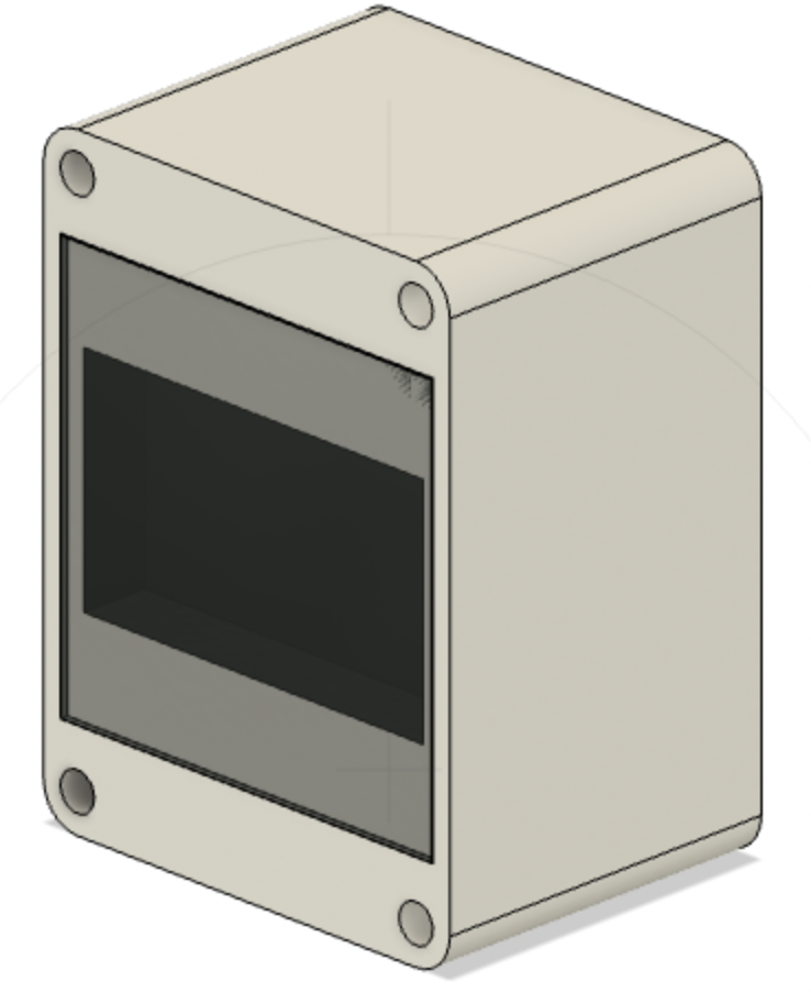

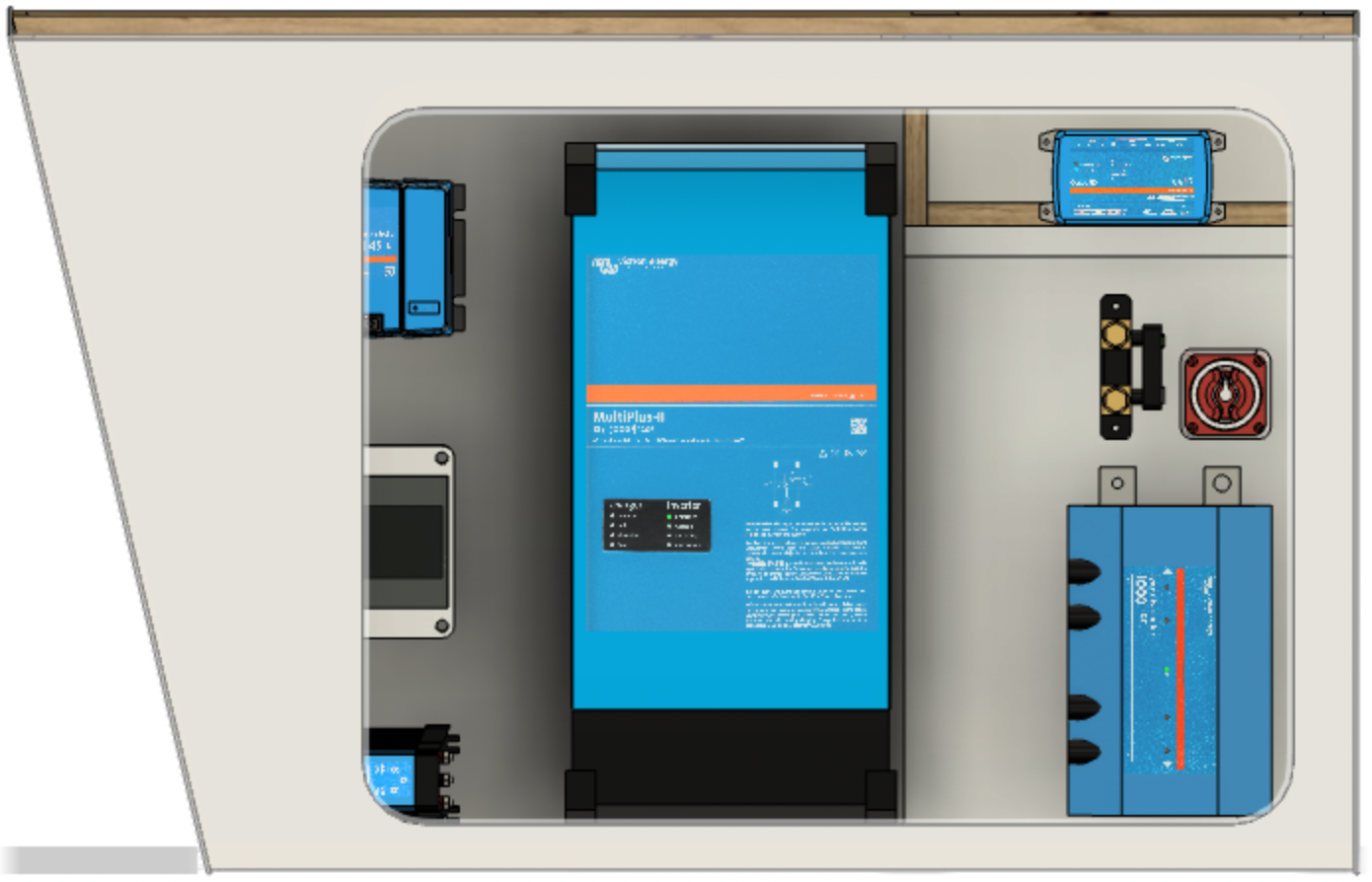
This modeling effort enabled us to place each component, move them around, ensure adequate spacing, etc. The implementation illustrated in Figures 5 and 6 was achieved by adding a wall in our pass-through storage space and placing the modeled components. As previously mentioned, we may have to implement a 12 V alternative by removing the DC-DC converter and adjusting fuse values appropriately.

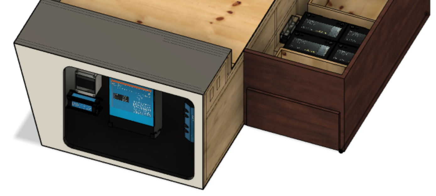
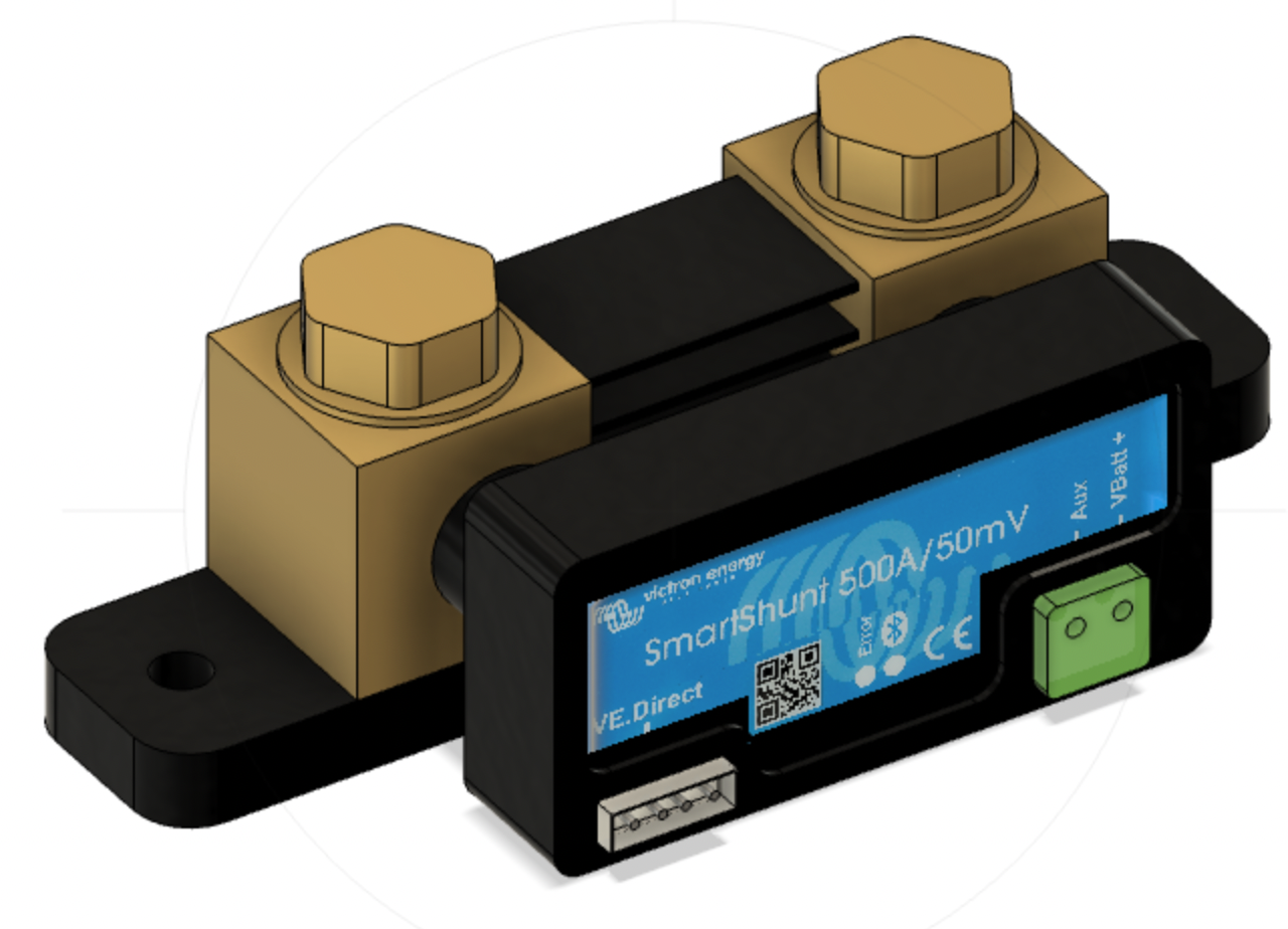
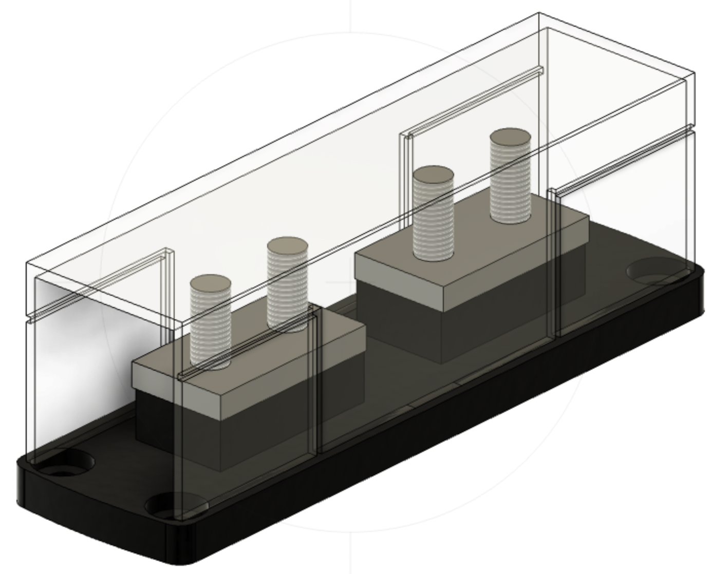
As previously mentioned, the battery bank will be located between the drawers in the under-bed storage area. In addition, we’ll build a small shelf near the batteries where our 300 A Class T fuse will be located. The battery cables will pass through the thin wall between the under-bed area and the pass-through storage area and then travel down to the left in Figure 7 until they reach the battery switch and SmartShunt.
Summary
In this post, we discussed our alternative 12 V design and modeled the physical spaces and components in the hope that we get it all right the first time around. This may be an optimistic goal, but having this detailed plan in hand will enable small projects to fit more seamlessly together. Now the work begins.