This is the tenth and last post describing our RV power system. Our previous post described the final design and some of its characteristics. This post summarizes the system’s performance on our first overnight outing. First, for convenience, we briefly describe the final system. Next, we describe our outing and associated conditions and finally explain the system’s performance.
Final System
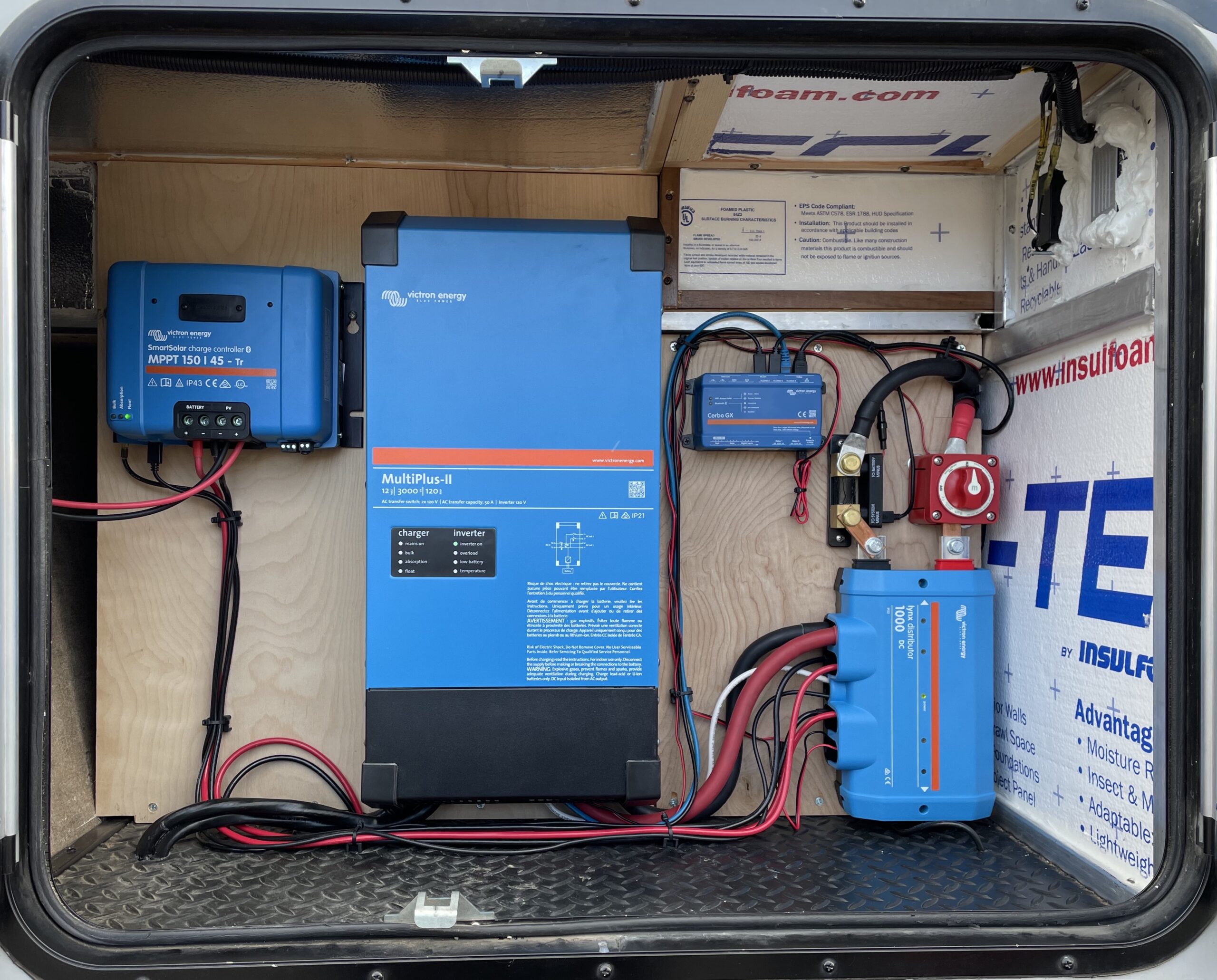
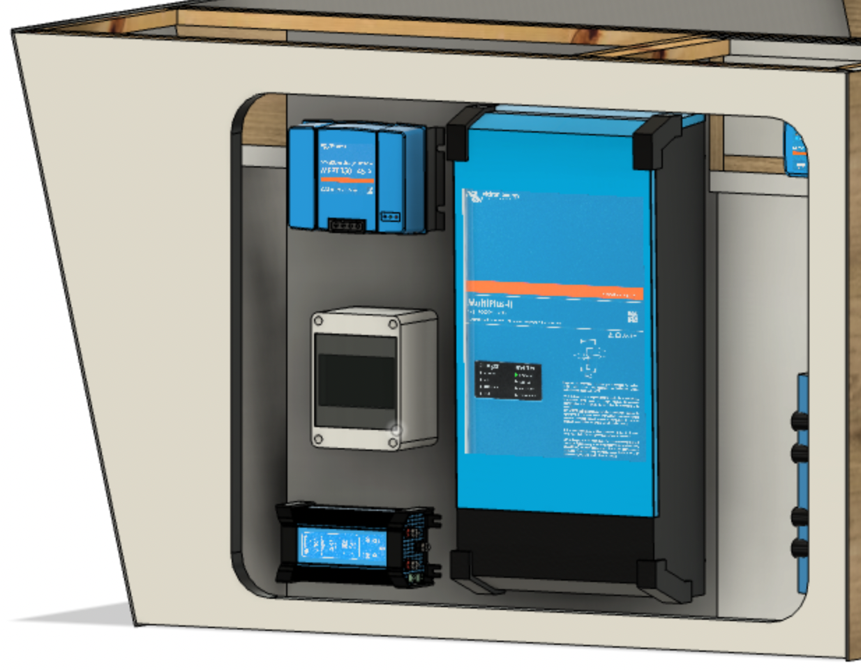
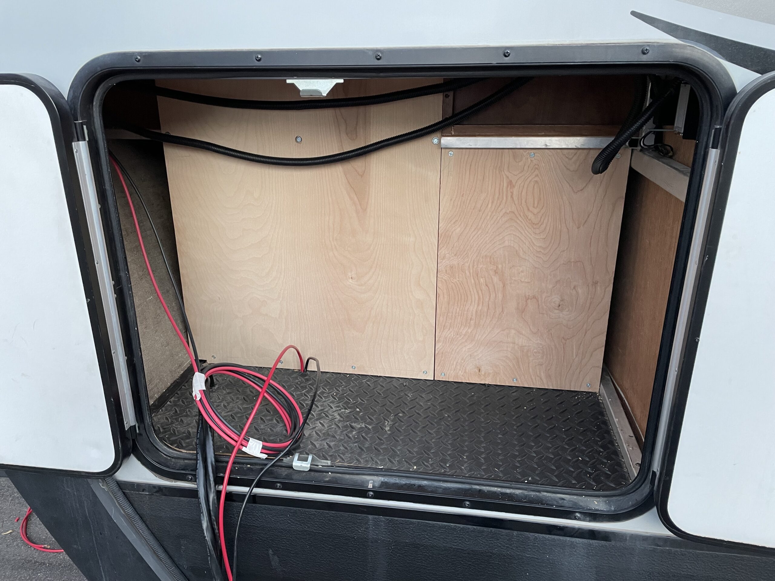
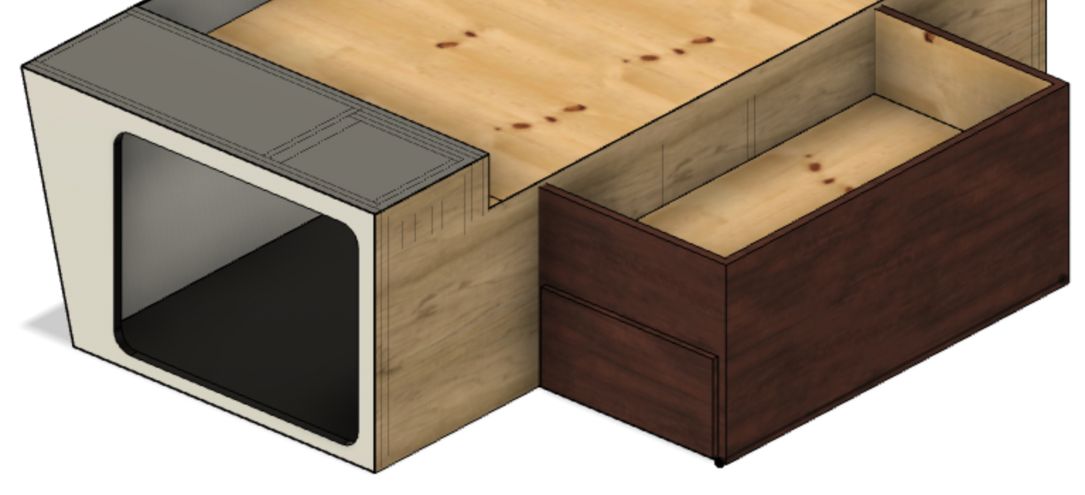
Our power system fits within the left pass-through storage area, illustrated in Figure 1.
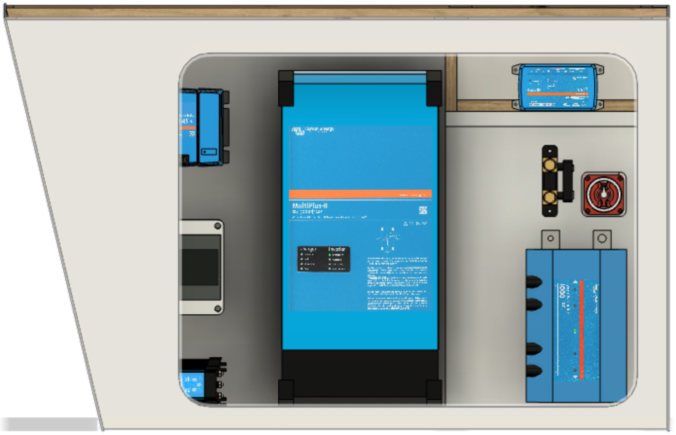
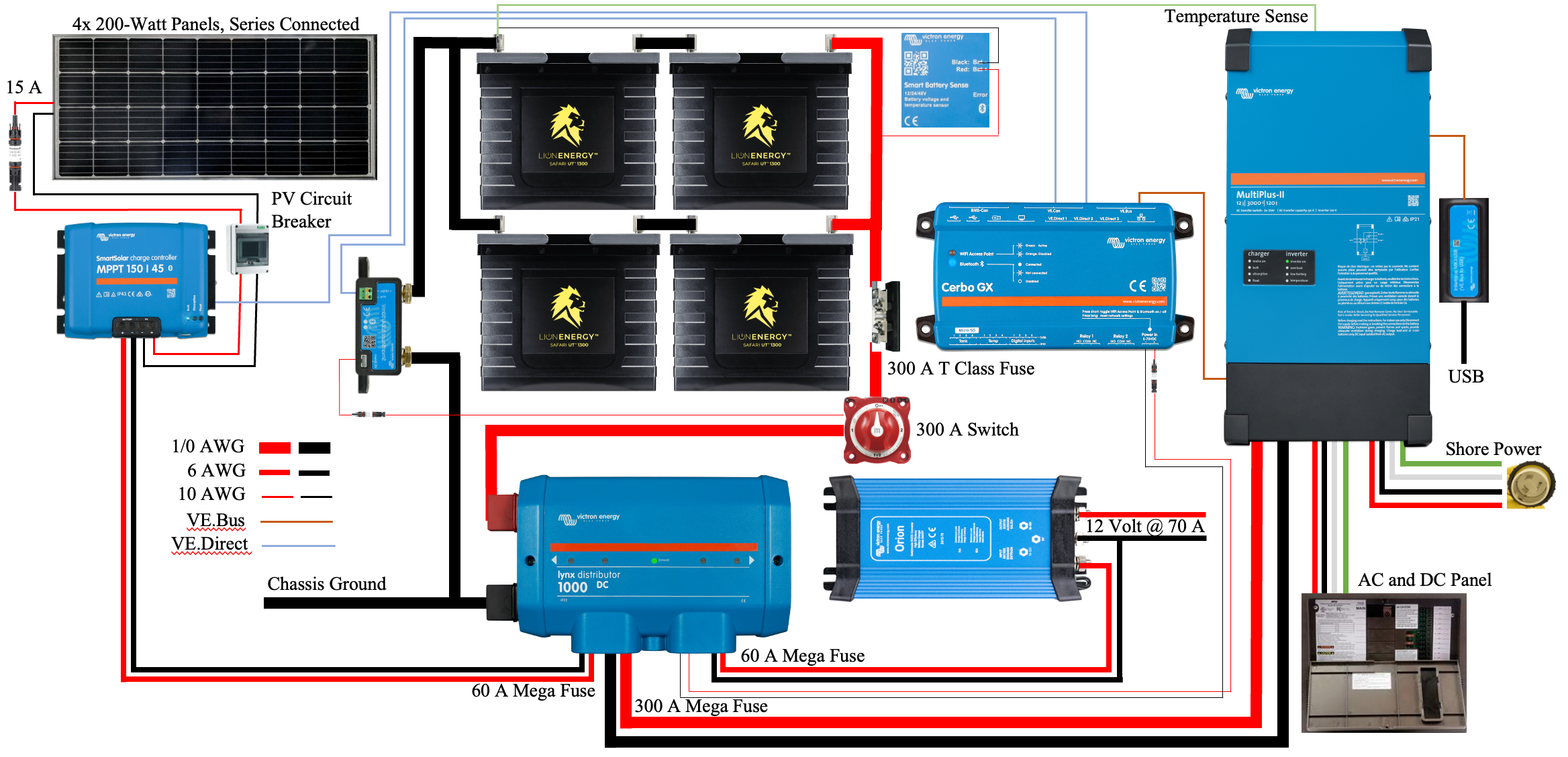
Figure 1 illustrates our complete power center providing 800 W of solar, 360 Ah of Lithium-ion batteries, and a 3kVA invert/charger.
Figure 1 illustrates the major components of our system. There are seven major components illustrated from upper left to lower right:
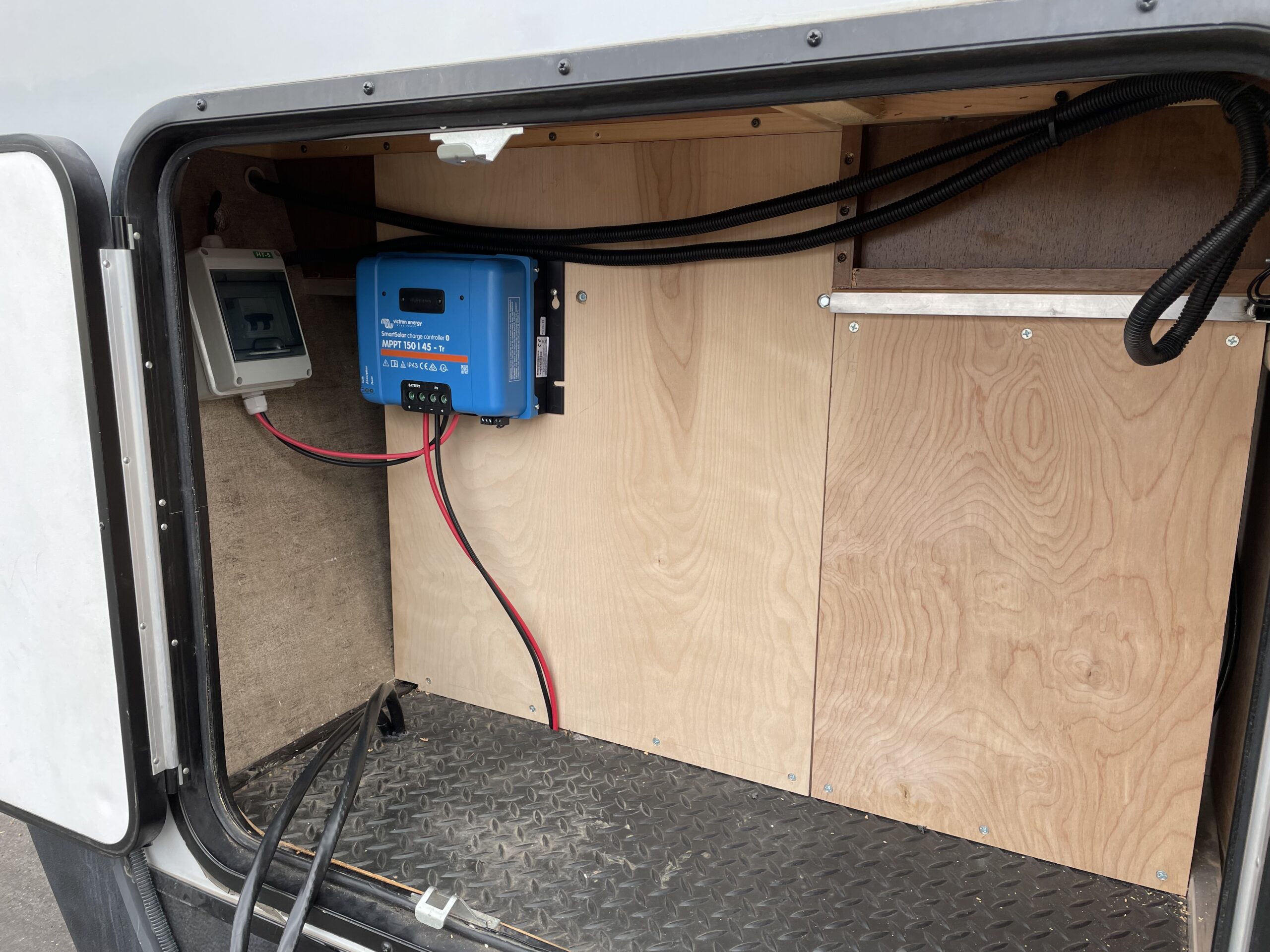
Solar PV disconnect switch
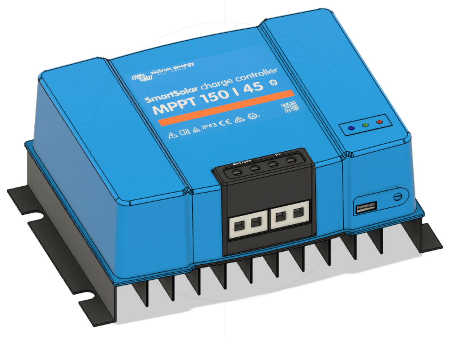
Victron SmartSolar 150/45 solar charger
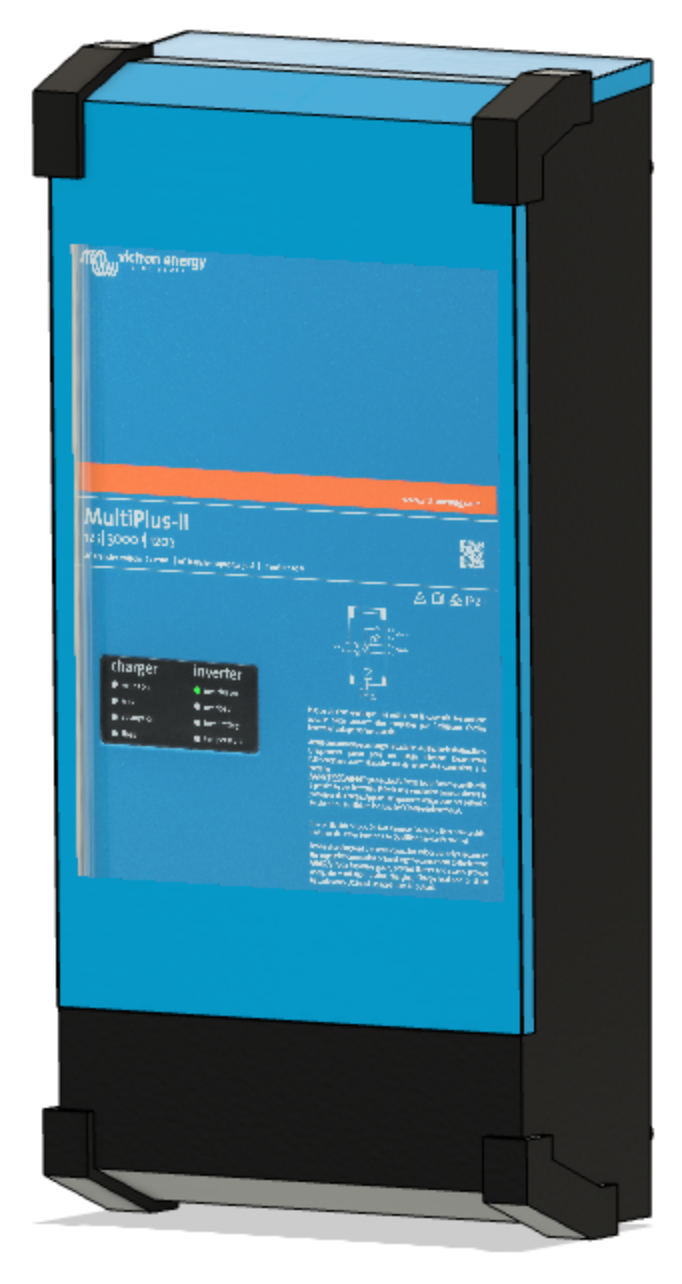
Victron MultiPlus-II 2x 120V inverter/charger
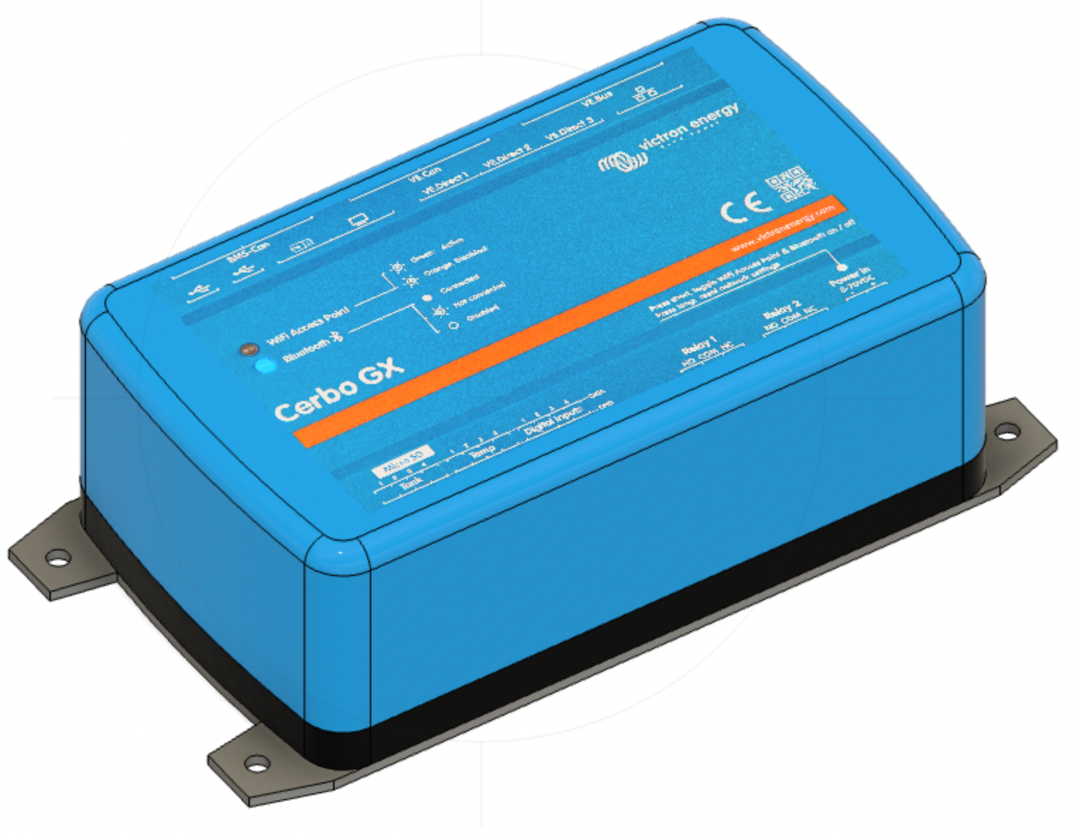
Victron Cerbo GX monitoring system
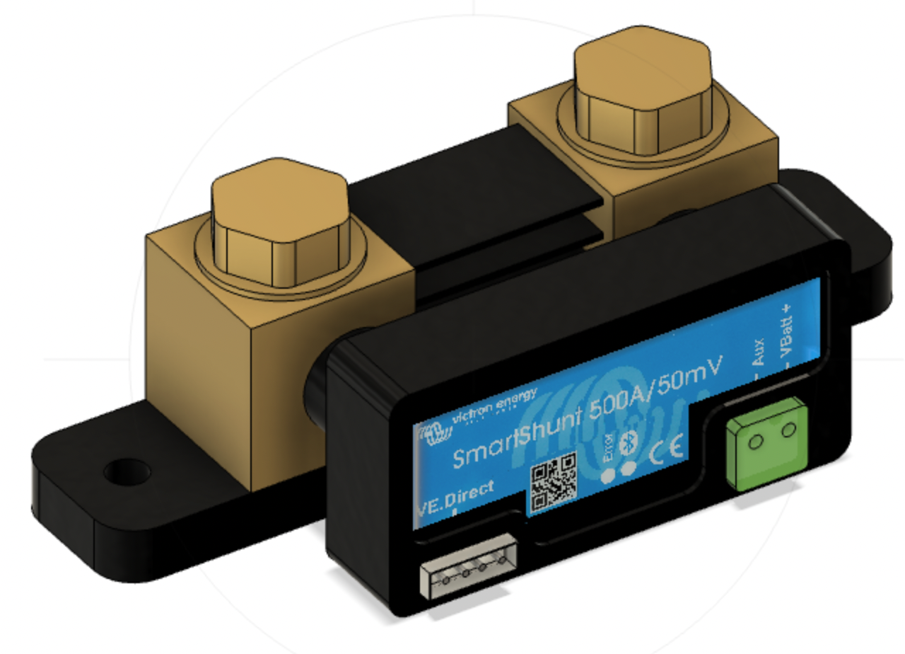
Victron SmartShunt
Blue Sea battery switch
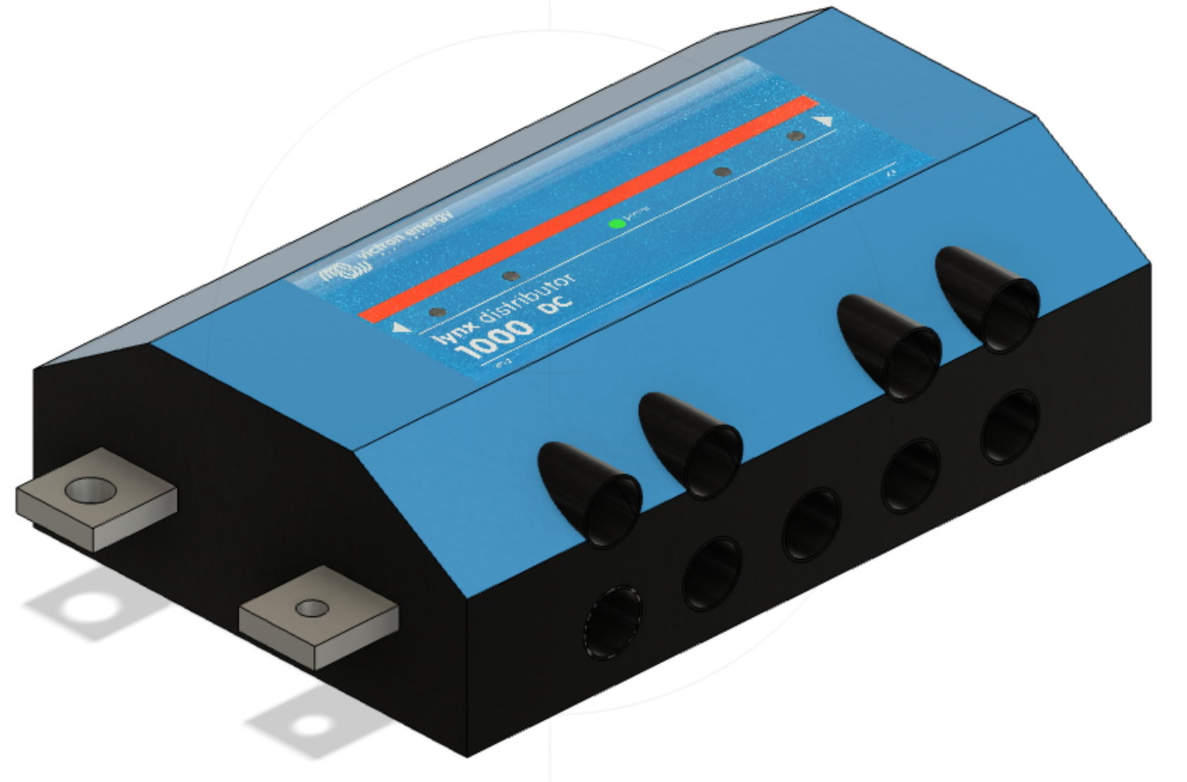
Victron Lynx Distributor
Our 360 Ah battery bank is behind and to the right of this location. The solar charger and the SmartShunt attach to the Cerbo GX via VE.Direct cables. The battery voltage monitor (mounted on the battery bank) and the MultiPlus-II connect to the Cerbo GX via two VE.Bus cables.
Our Outing – Red Canyon, Utah
We spent two nights in Red Canyon Campground in southern Utah in late April. This outing is described in more detail in another post. The daytime temperatures were in the mid-60s, and the lows were in the low-20s. The sun was bright the first day. We had a couple of hours of good sunlight on the second day and then overcast with rain.
Performance
With the nighttime temperatures in the 20s, our furnace periodically ran to keep the trailer at approximately 65 degrees. In addition, we watched television for several hours at night, used lights, and charged a couple of phones, watches, and an iPad. With all of these devices running and charging, we consumed nearly 80 Ah of our 360 Ah battery bank. Our batteries were replenished after just a few hours of good sunlight.
Early in the day, the solar charging system produced about 360 W. I decided to check the cleanliness of the solar panels and was shocked to find them coated in mud. It was thick enough that I could not remove it without a significant amount of water. After cleaning the panels, the system produced just over 500 W. A little water and elbow grease pay off.
Figure 2, our electric fireplace.
After a 5 mile hike, we returned to find our RV an uncomfortable 81 degrees. We flipped on the AC and set the thermostat to 75. The AC drew a constant 1100 W and ran for approximately 30 minutes. Later that evening, the temperature in the RV dipped down to about 68 while we were still up and around, so we turned on the electric fireplace. That unit drew nearly 1400 W but warmed us right up. We tried a few other electric devices to see the practicality. The refrigerator on electric power drew about 22 A, my wife’s curling iron was no big deal at 200 W, and I’ve tried the microwave before at just over 1000 W.
It is a pleasure to use all of our systems without generating noise. We can use the AC, microwave, and TV after campground quiet hours without worrying about bothering others. However, it is funny watching us adapt to this new world. Are we content toasting our bread in the broiler? Of course not; we need a toaster because we can have one! I am sure we’ll add a hairdryer and who knows what else. Nevertheless, I am pleased with the outcome and the comfort it has added to our lives.
This is the ninth post of a series of articles documenting and describing our RV electrical upgrade. Our previous post in this series described a simplified model of our battery bank, the wiring of our system, the resistance contributed by each component and associated cables, and the expected system voltage drop. Our goal is to keep our voltage drop to 2.5% or less as recommended in Victron’s Wiring Unlimited. This post describes the outcome, reports actual voltage drop measurements, and compares these with those calculated previously. Finally, we evaluate our final results regarding our initial goals, point out a few things we’d do differently, and conclude. For those interested, this page lists the parts, equipment, and tools we used to build our power system.
Initial Design
Figure 1 illustrates the power system proposed in a previous post.
The power system we built, illustrated in Figure 1, was initially proposed in one of our first posts in this series. In our previous post, we introduced the critical path of this system consisting of the circuit from the battery bank to the inverter/charger and back, illustrated in Figure 2.
Figure 2 illustrates the components and cables that make up our system’s critical path and associated resistance values.
Figure 2 includes the measured resistance of each cable and component, such as the 400 A class T fuse, battery disconnect switch, shunt, 400 A mega fuse, and the Lynx Distributor busbar system. These resistances are assumed to be worst-case values as we rounded up measurements and the measurement device’s connection to each component was simply the tension applied by the spring-loaded probes. The total measured resistance of components and cables around our system’s critical path is 1.77 mΩ. With this resistance, we concluded that our system should be capable of providing just over 180 A while remaining at or below our 2.5% voltage drop goal.
Final System
After considerable cold winter work, our design came to fruition. As previously described, our power system fits within the left pass-through storage area, illustrated in Figure 3.
Figure 3 illustrates our complete power center providing 800 W of solar, 360 Ah of Lithium-ion batteries, and a 3kVA invert/charger.
Figure 3 illustrates the major components of our system. There are seven major components illustrated from upper left to lower right:
Solar PV disconnect switch
Victron SmartSolar 150/45 solar charger
Victron MultiPlus-II 2x 120V inverter/charger
Victron Cerbo GX monitoring system
Victron SmartShunt
Blue Sea battery switch
Victron Lynx Distributor
Our battery bank is behind and to the right of this location. The solar charger and the SmartShunt attach to the Cerbo GX via VE.Direct cables. The battery voltage monitor (mounted on the battery bank) and the MultiPlus-II connect to the Cerbo GX via two VE.Bus cables.
We used a Victron MK3-USB device to program the inverter/charger for our specific setup and then used the remote console provided by the Cerbo GX to monitor the initial startup. After turning on the battery switch and the solar PV switch, the system immediately started providing inverted power to the RV, and the solar charger started charging the batteries. Next, using a halogen light and my wife’s toaster, we applied some moderate load to the system and took some readings, found in Table 1.
Battery Voltage
Inverter Voltage
Voltage Drop
Current (A)
Resistance mΩ
12.88
12.84
0.04
25
1.6
12.71
12.61
0.10
73
1.4
12.28
12.04
0.24
157
1.5
As expected, as the system current increases, the voltage drop experienced by the inverter/charger increases. We divided the voltage drop by the associated system current to calculate the system resistance. Averaging these three values, we note that the system resistance is 1.5 mΩ which is 0.27 mΩ lower than the measured 1.77 mΩ.
The system experienced a 0.24 V voltage drop with a 157 A load. A voltage drop of 0.24 V is a percentage voltage drop of just 1.9%, well below our limit of 2.5%. With a resistance of only 1.5 mΩ, we should be able to load our system to nearly 215 A without exceeding our 2.5% goal. These 5-10 minute load tests resulted in almost no heat generation by the inverter/charger or any system components. I am looking forward to more extended tests to see how hot things get.
Summary: How Did We Do
Nearly three months ago, we outlined our goals for our new power center in our first post on this subject. We desired the ability to use our microwave, television, and other 120 V AC systems without having to ruin our camping solitude with a generator. In addition, we wanted to minimize the intrusion of our generator while recharging our batteries. We determined that to meet our needs, we needed several items:
400 Ah of lithium-ion batteries
800 Watts of solar power
An inverter that is capable of producing nearly 3000 Watts of 120 V AC power
A battery charger that is capable of consuming our entire generator output to minimize charge time
We have nearly met each of these requirements. Instead of 400 Ah of batteries, we have 360 Ah, and instead of 3000 W of inverter power, we have 3000 VA or 2400 W continuous. We believe each is close enough to call this project a success. Perhaps more importantly, we learned a lot on the journey and had a lot of fun. If our RV needs to be restored to what we had before this project, here is a brief description of the required tasks.
We did a couple of things right and a few we’d do differently with the new knowledge we possess:
We can’t properly express how great the copper bar approach to connecting the battery disconnect switch and the SmartShunt to the Victron Lynx Distributor is. Using a short segment of 4/0 wire and a lug at each end results in a rather long connection. The copper bar approach saves space, looks clean, and in our cramped environment made our layout possible. You could save ten bucks if you want to make your own, but we saved ourselves the cutting, drilling, and the likely mistakes and bought a pair.
I wouldn’t have initially skimped on our torque wrench purchase. Our fitst purchase had a torqu range of 10-100 ft-lbs and barely registered when being used at the low end. We ended up twisting a bolt head on a battery lug clean off. This was dangerous and could have resulted in a bolt being unretrievable from an expensive battery. Fortunately, just enough bolt was left to enable its removal with a pair of vicegrips. We love our second torque wrench, the Park Tool TW-6.2.
We would definitely use boat/marine wire instead of the 6/3 Romex that we installed. Our RV, like most, is full of Romex making us comfortable that this was a reasonable choice. In addition, 6/3 Romex contains stranded conductors, but not like ultra flexible boat/marine wire such as Ancor’s Triplex Cable.
We would have used lugs suggested by Victron Energy. The 4/0 sized lugs we used are great, but don’t fit very well within the Victron Lynx Distributor. I suspect, but have no evidence that the lugs they suggest would fit much better.
We’re done, it looks clean and neat, and above all else, it works!
This post is the eighth of an ongoing series of articles documenting and describing our RV electrical upgrade. Our previous post in this series described some non-power-related improvements to the pass-through storage area. These improvements included thermal insulation and an acquired storage system. In this post, we describe a simplified model of our battery bank, the wiring of our system, the resistance contributed by each component and associated cables, and the expected system voltage drop. Our goal is to keep our voltage drop to 2.5% or less as recommended in Victron’s Wiring Unlimited.
Our Battery Bank
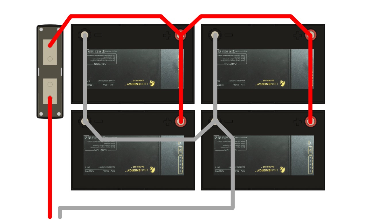
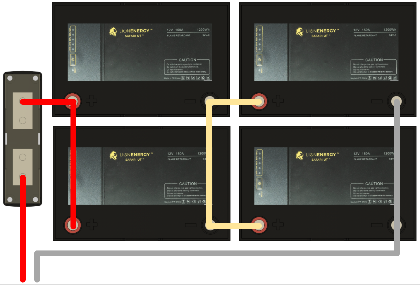
Figure 1 illustrates the Halfway parallel battery configuration.
We previously discussed the idea of installing a 24 V system to reduce system currents, but we have determined to stay with a 12 V system. A 12 V system keeps things straightforward and reduces our time to completion. We’ll use the “Halfway” parallel configuration for our battery bank as described in Wiring Unlimited and illustrated in Figure 1. We chose this approach because it simplifies the cable layout given the physical placement of our batteries.
The Halfway configuration ensures the circuit path from each battery’s positive terminal, through an otherwise balanced load, and back to the same battery’s negative terminal is the same length for each battery. Strictly speaking, the resistance, measured in ohms (Ω), should be kept equivalent and minimal, but length is correlated to resistance and is easier to measure. Our design will opt for wiring convenience over strict adherence to keeping each path equal in length. Using wires of various lengths will introduce minor deviations from the ideal.
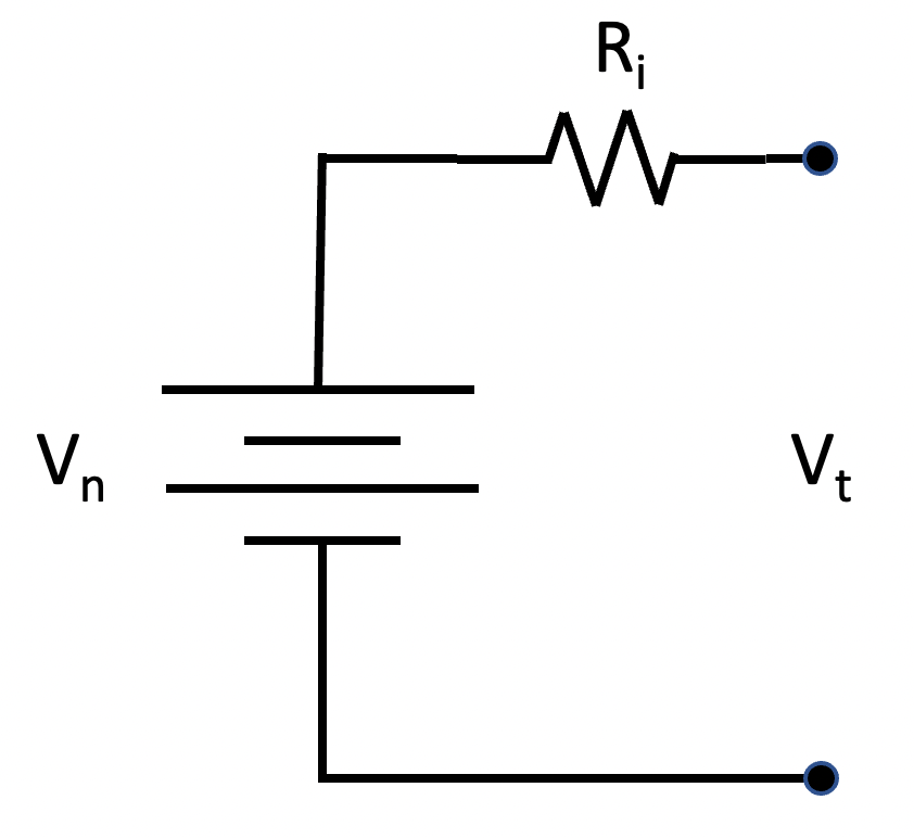
Figure 2 illustrates a simple battery model consisting of an ideal/imaginary battery and a resistor representing the internal resistance of a real-world battery.
We developed a simplified model of our battery bank to determine if our design is viable. As the load on a battery increases, the voltage measured at the terminals decreases due to internal battery resistance. The battery model illustrated in Figure 2 includes an ideal battery and a resistor representing the battery’s internal resistance. Vn represents the battery’s nominal voltage, Ri represents the battery’s internal resistance in ohms, and Vt represents the voltage measured between the battery’s terminals. This model predicts that as the current draw from the battery increases, the voltage seen at the terminals will be lower than the nominal voltage; Vt = Vn – Ri*i, where i is the current drawn from the battery measured in amperes.
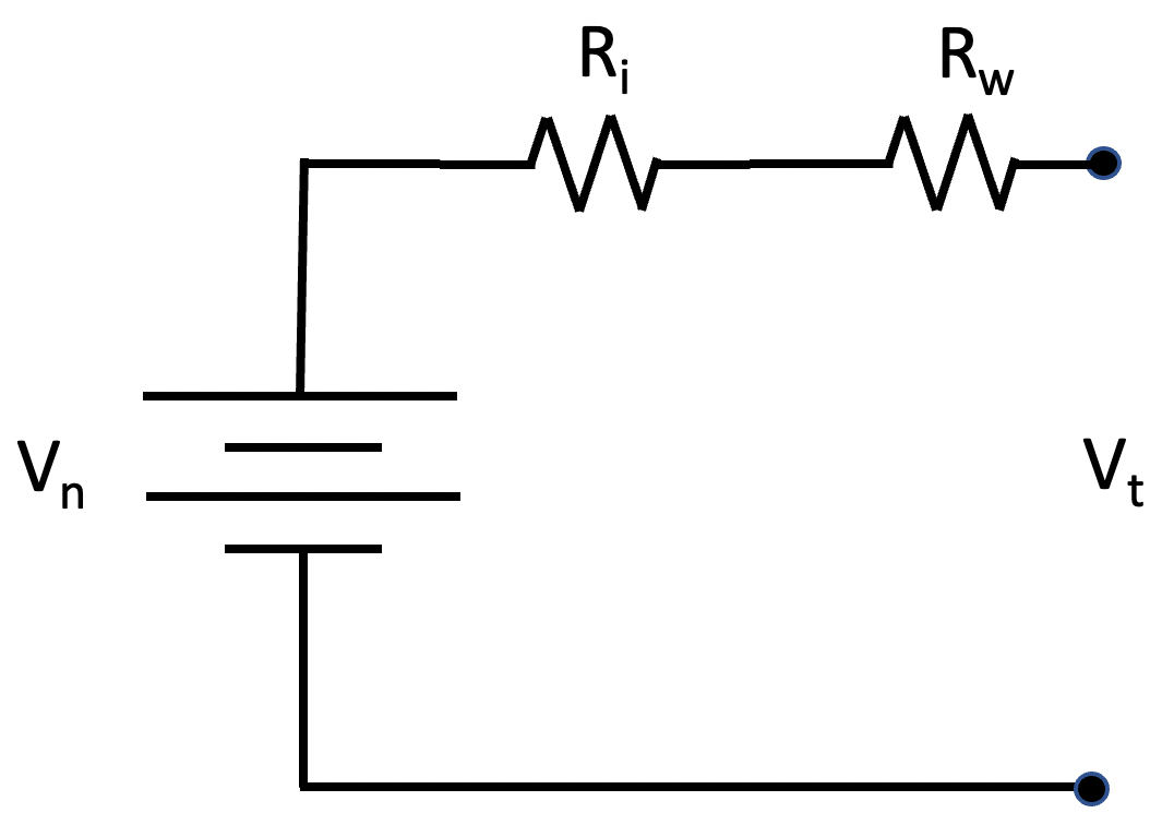
Figure 3 illustrates the addition of wire resistance to the model of Figure 2.
Our battery bank consists of four batteries interconnected with cables. These cables add additional resistance, Rw, to the system, as illustrated in Figure 3. Four of these models, each with a potentially different value for Rw, connected in parallel represent our battery bank.
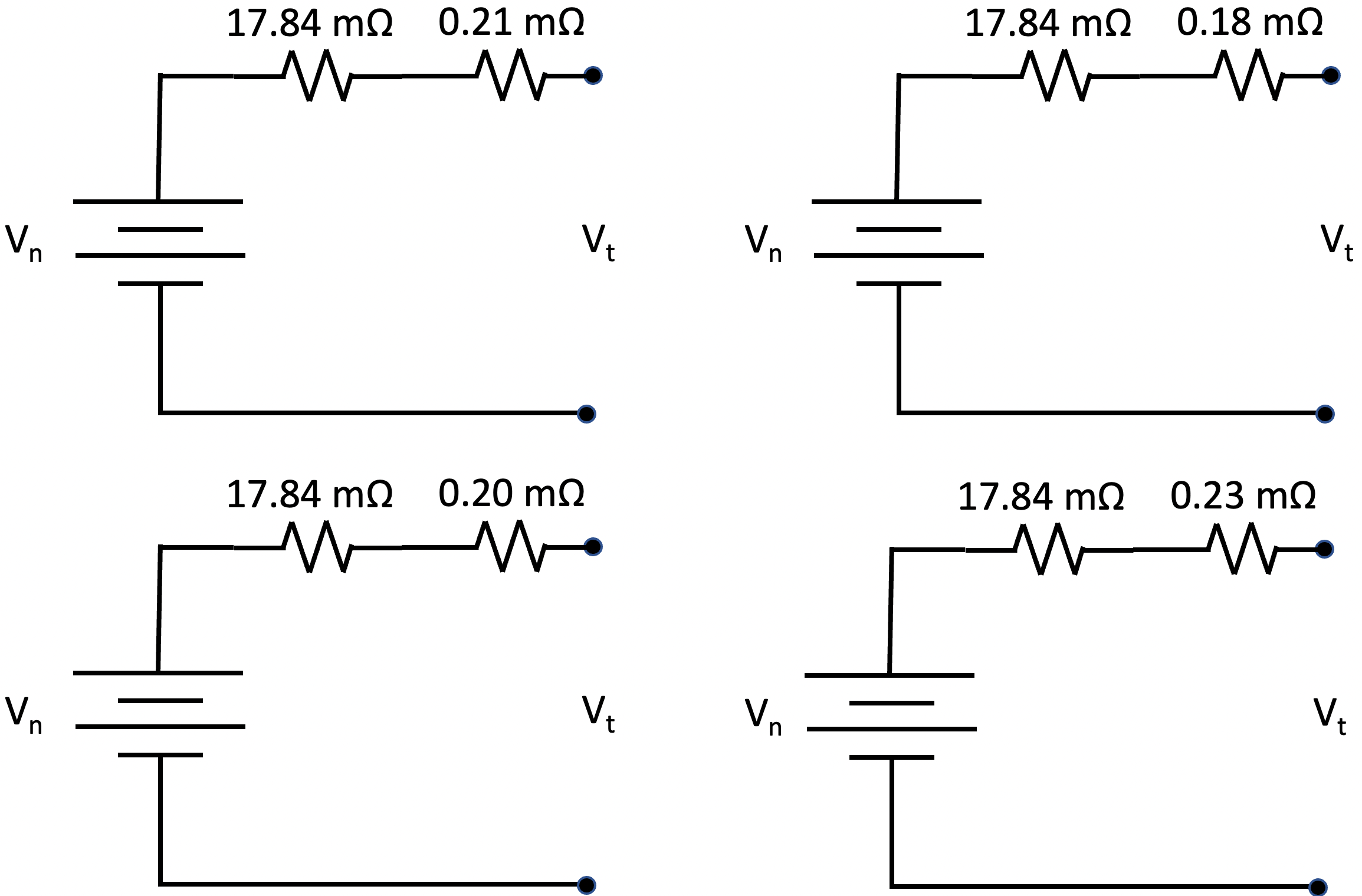
Now let’s put some numbers to these models and see what we expect from our battery bank. Lion Energy reports that the internal resistance of their UT 1200 battery is 17.84 mΩ. Using a Keithly 2450 SourceMeter, we measured the resistance of each 4/0 cable we created. We crimped lugs to both ends of each cable and measured each cable’s resistance from the center hole of one lug to the center hole of the other. There are two 11″ cables measuring at 0.10 mΩ for the red cable and 0.13 mΩ for the black cable. There are four 6.5″ cables measuring at 0.08 mΩ for the two red cables and 0.10 mΩ for each of the two black cables. Figure 4 illustrates the simplified models of our four batteries using the Lion Energy reported battery internal resistance and the measured values of the 4/0 wires interconnecting our batteries.
Figure 4 illustrates a model for each of our four batteries. Each battery has the same internal resistance, but the wiring making up the battery bank gives each battery a slightly different value for Rw.
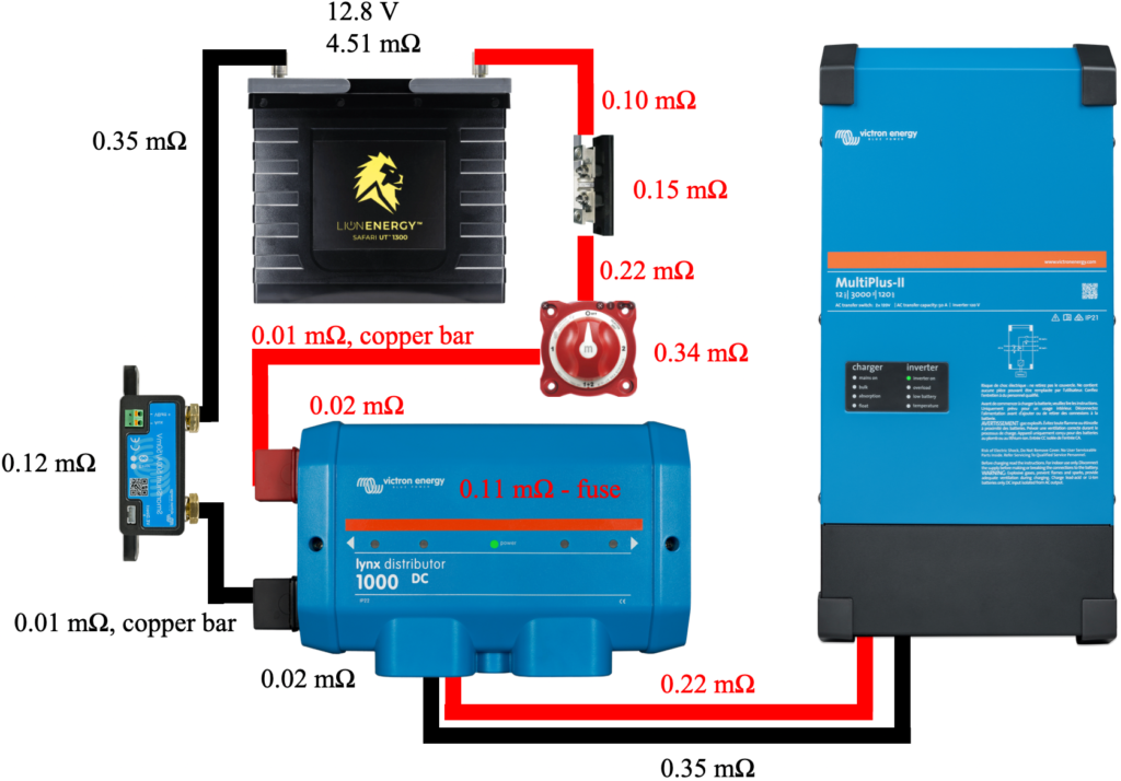
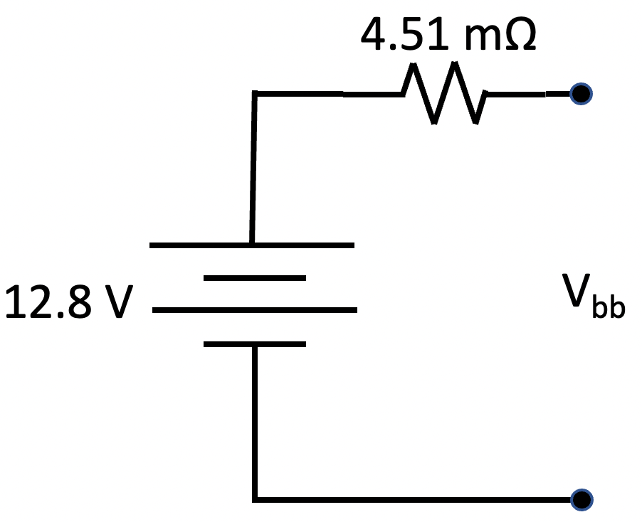
Figure 5 illustrates our simplified battery bank model.
After connecting the four models illustrated in Figure 4 in parallel, circuit analysis and simplification results in the model shown in Figure 5. In this model, the resistance of the entire battery bank is 4.51 mΩ, with the nominal voltage being 12.8 V. Vbb represents the voltage seen across the two battery bank terminals that connect to the remainder of our power system.
Note that the interconnect resistance is relatively small compared to the internal resistance of each battery. If the wiring resistance were zero, the model for the battery bank would be trivial to acquire. The battery voltage would have the value Vn, and the series resistor would be the internal resistance of a single battery divided by the number of batteries. With an internal resistance of 17.84 mΩ, the ideal series resistor would have a value of 4.46 mΩ. Note that our model’s resistor has a value of 4.51 mΩ, just a bit more than the ideal. We could see currents approaching 275 A in our system. At 275 A, our model predicts that Vbb would be 1.24 V lower than Vn, or 11.56 V, while the ideal model predicts a Vbb of 11.57 V, not a significant difference. We expect typical maximum currents of 150 A. At this level, we expect Vbb to be 0.68 V lower than Vn, or 12.12 V.
Our Power System
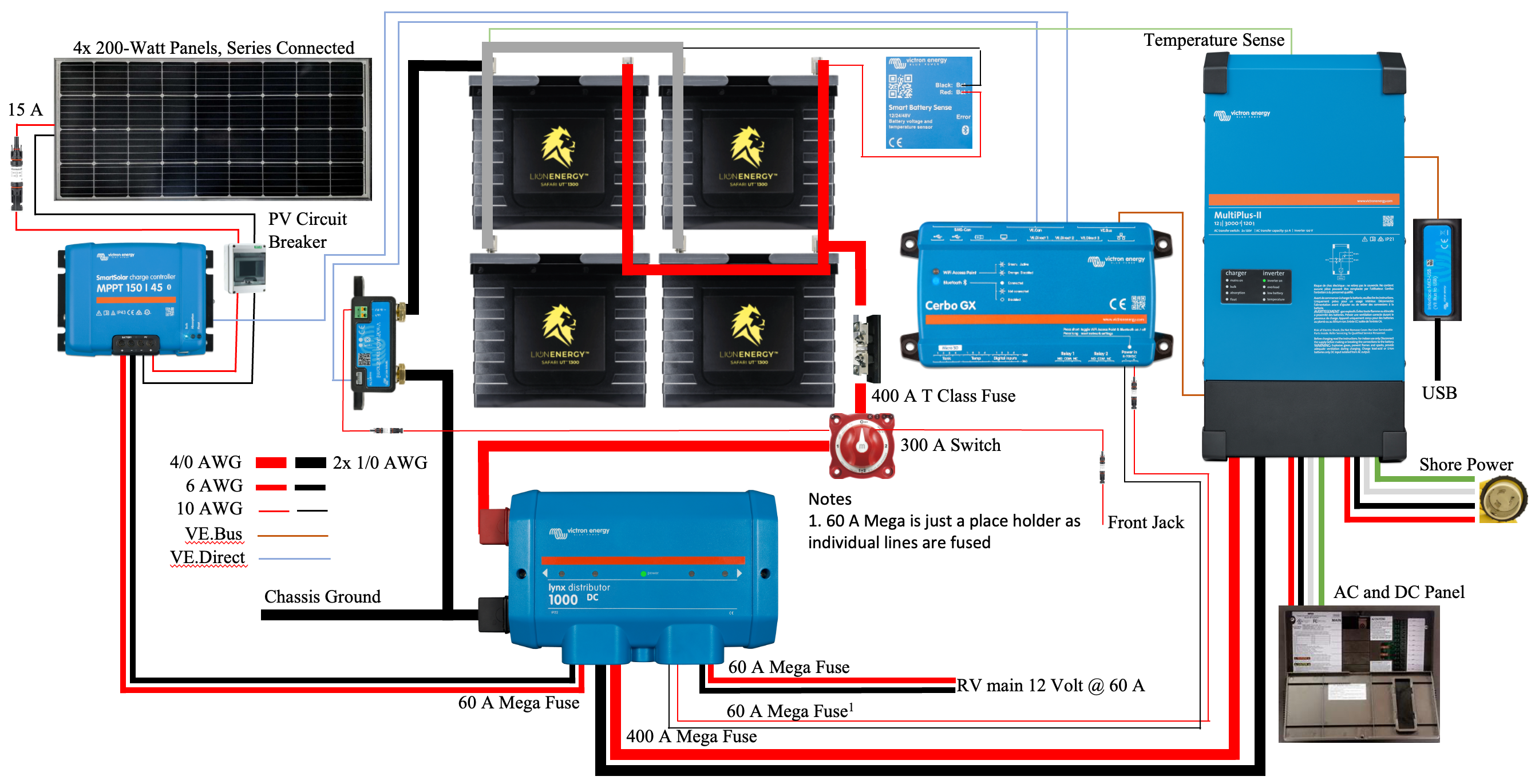
Figure 6 illustrates our entire power system.
The power system we are endeavoring to build is described in a previous post and illustrated in Figure 6. The critical path in our system is the circuit from the battery bank to the inverter/charger and back. The other system components are essential but generate or consume far less power than the inverter/charger, resulting in lower currents and associated voltage drops.
Figure 7 illustrates the components and cables that make up our system’s critical path and associated resistance values.
Figure 7 illustrates a simplified schematic of our system, including only the components and 4/0 cables involved in the high current critical path. These 4/0 cables should be capable of carrying 400 A of current. The figure also includes the resistance of each cable and components such as the 400 A class T fuse, battery disconnect switch, shunt, 400 A mega fuse, and the Lynx Distributor busbar system. The cable resistances were measured using the method previously described. Component resistances were obtained by properly torquing a cable of known resistance to each component connection, measuring the resistance from the end of one cable to the end of the other cable, and subtracting the resistance values of the two cables.
In this simplified schematic, we have replaced the battery bank with an image of a single battery with the voltage and resistance values computed using our battery bank model. All resistance values are included in Table 1.
Component
mΩ
13" 4/0 red cable with lugs crimped to each end. Connects battery bank to fuse holder.
58" 4/0 black cable with lugs crimped to each end. Connects SmartShunt to battery bank.
0.35
Total circuit resistance from battery bank
1.77
While not critical to this work, it is interesting to note that according to this table, a 1000′ segment of room temperature 4/0 copper wire has a resistance of 50 mΩ. This implies that our 13″ cable connecting our battery bank to the rest of our system should have a resistance of 0.054 mΩ, yet it measures in at 0.10 mΩ. The crimped lugs contribute the difference of 0.046 mΩ. This implies that each 4/0 crimped lug contributes 0.023 mΩ of resistance. Another interesting fact is that our black 4/0 wires used in our battery bank wiring have a slightly higher resistance than their red equivalents. For example, the black 6.5″ cables have a resistance of 0.10 mΩ while the equivalent red cables have a resistance of 0.08 mΩ.
The total resistance of components and cables around our system’s critical path is 1.77 mΩ. With the inverter powering its maximum load of 3 kVA and just before system shutdown with a battery voltage of 11 V, the system currents would be approximately 273 A. Our system resistance at these high currents would result in a voltage drop of 0.48 V. However, no single system in our RV consumes this much power, and two or more of the large systems would exceed the maximum limit. We expect currents in the 150 A range when either our air conditioner or our microwave oven are operating. At 150 A, our voltage drop will be 0.27 V or 2%, a reasonable figure. Our system should be capable of providing just over 180 A while remaining at or below our 2.5% voltage drop goal.
Summary
Our goal is to create an RV power system that meets our design objectives. One of our goals is to satisfy our power needs while suffering less than a 2.5% voltage drop due to system resistance. This goal will reduce the likelihood of excessive system ripple and other undesirable characteristics. Our system has a critical path resistance of 1.77 mΩ and should supply up to 180 A while staying below a 2.5% voltage drop; this should meet our needs and validate our design’s viability. Next up is the remainder of the implementation.
This post is the seventh of an ongoing series of articles documenting and describing our RV electrical upgrade. Our previous post in this series described the original shore power wiring and our improvements. In addition, we discussed a severe flaw that was difficult to find but eventually corrected. In this post, we describe non-power-related improvements to the pass-through storage area. These improvements include thermal insulation and an acquired storage system.
Thermal Insulation
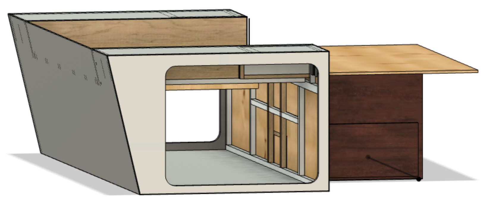
Figure 1 illustrates our pass-through storage area and shows how the ceiling and rear walls of this area are adjacent to the living areas of the trailer. The ceiling of the storage area is the bottom bed support.
Only thin materials separate the ceiling and rear wall of our pass-through storage area from the bedroom area of our trailer, as illustrated in Figure 1. These materials provide little thermal insulation between the near outdoor conditions of our storage area and our living quarters. During colder weather, the front and top of each nightstand and the sides and bottom of the upper portion of the bed get cold.
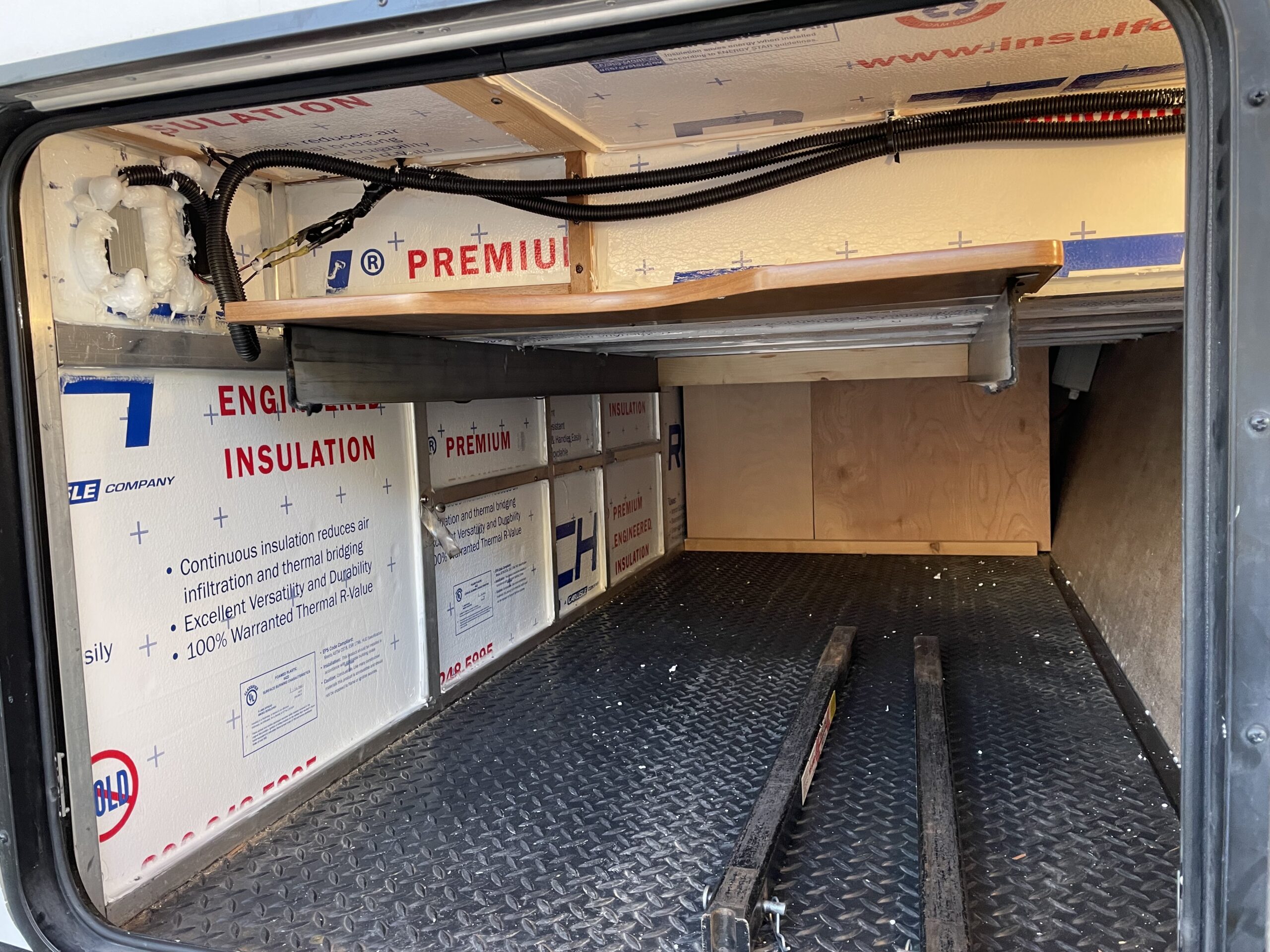
Figure 2 illustrates the foam panels added to the rear wall and ceiling of the pass-through storage area.
Jason Evans‘ post inspired us to mitigate this issue by insulating our pass-through area. Jason reported using R 1.93 insulation panels, while we chose to use R 3.85 panels that offer twice the insulation at, you guessed it, nearly twice the price.
Our space required nearly two 4′ by 8′ sheets of material. First, we used a box cutter and straightedge to subdivide each panel. Then, we gently pushed each piece into position and caulked them to keep them from falling out of place. We thought this was particularly important for those loosely hanging from the storage area ceiling. Figure 2 illustrates the complete installation. We also used expanding foam to seal around the 120 V outlets and USB port outlets on each nightstand. These modifications should help keep the cold and heat out and reduce the noise of our soon-to-be-added inverter/charger.
Sliding Storage Tray
When we built our power center, we inadvertently created a bit of a storage dilemma by adding the wall visible at the far end of the pass-through storage area in Figure 2. As a result, we eliminated easy access to the far end of the nearly 7′ deep remaining storage space accessible only via the remaining hatch. This depth would make it very difficult to get items from the far end of the area.
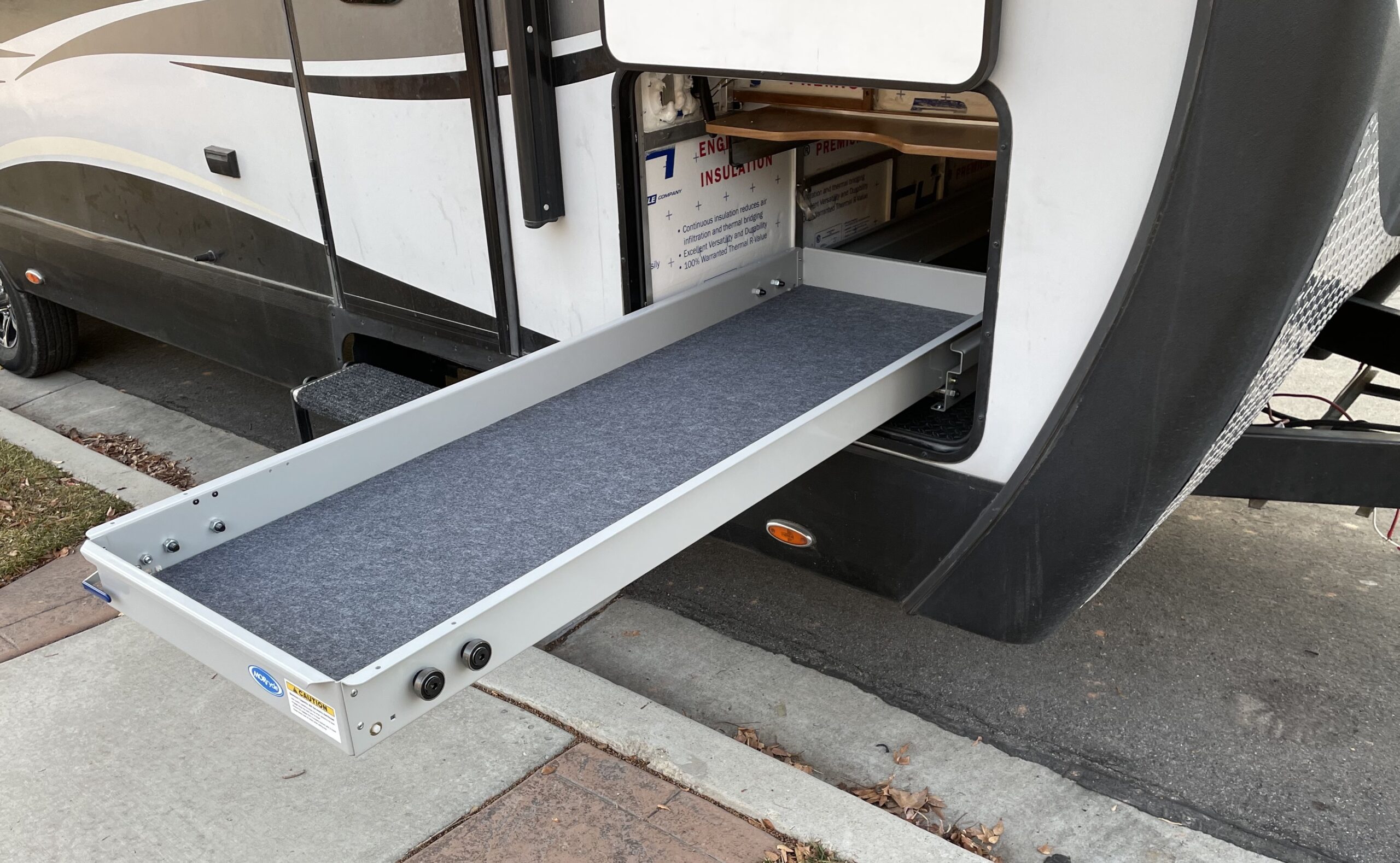
To facilitate retrieving items from this area, we have acquired a MORryde CTG80-2672-2DW 80% extension cargo tray, illustrated in Figure 3. This tray is 26″ wide and 72″ long, perfectly fitting our space. In addition, the tray walls are 4.3″ tall, and the tray floor comes pre carpeted. The structure bolts to the bottom of our storage area, and the tray rides on heavy-duty roller bearings and can support 500 pounds of gear. Working on electrical wiring in that area is now simple. I pull out the cargo tray, lay on it with my tools, and pull myself in.
Figure 3 illustrates the MORryde CTG80-2672-2DW fully extended.
MORryde offers 60% extension trays that only move in one direction, and while they support heavier loads, they also cost a bit more than the 80% extension trays. The 80% MORryde extension trays are intended to slide in both directions, but we won’t use this feature in our application. With the tray extended to 80% of its length, as illustrated in Figure 3, little of the tray remains within the storage space, making the extraction of items simple. Less drawer would stay within the storage space in some installations, but we chose to set ours back from the door nearly 8 inches (see Figure 4).
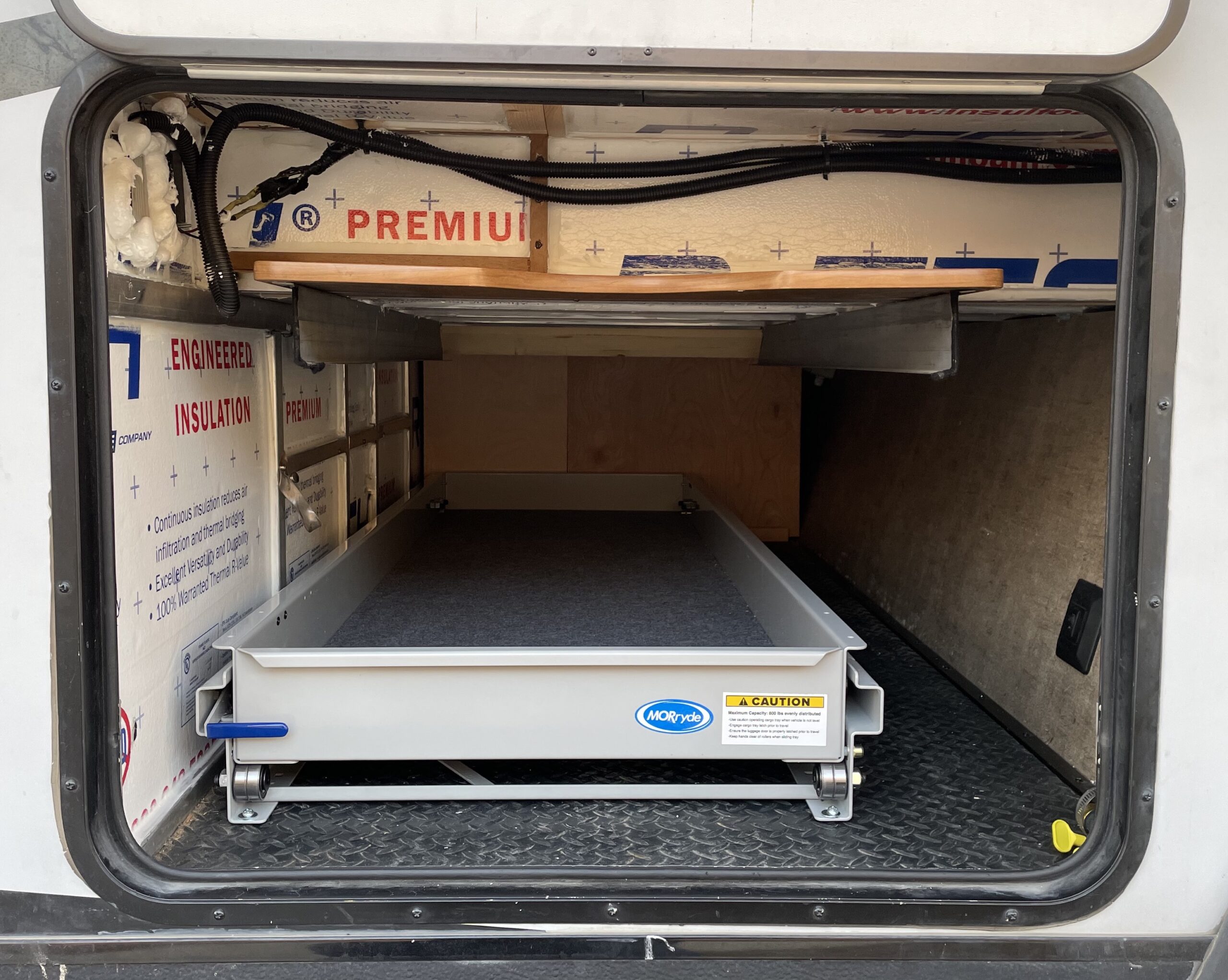
Figure 4 illustrates the MORryde cargo tray locked into place.
Another nice feature of the MORryde cargo trays is that they lock into place when stowed away. It is a simple matter to lift the blue handle on the unit’s left while pulling the tray out. When you push the tray back in, it locks in place. Figure 4 also illustrates how we chose to mount our tray towards the rear of the RV to leave space for long items we don’t often access. We’ll also take advantage of the wall space to the left and right of the tray for hanging light and narrow items such as axes, hammers, jack handles, etc. While this is an unexpected additional cost to our power upgrade project, it will create a better storage experience.
Summary
This one was the most obvious and straightforward of all the projects we’ve tackled thus far. We cut some foam to size, put it in place, caulked the seams, and installed a pre-constructed cargo tray. Frankly, it was refreshing to begin a project with few unknowns, with an obvious list of steps to accomplish, and resulting in an end product that will add value to our camping experience.
This post is the sixth of an ongoing series of articles documenting and describing our RV electrical upgrade. Our previous post in this series described the Victron Energy Lynx Distributor and a minor modification we made to it to meet our needs better. This post describes the original shore power wiring and our improvements. In addition, we discuss a severe flaw that was difficult to find.
Shore Power
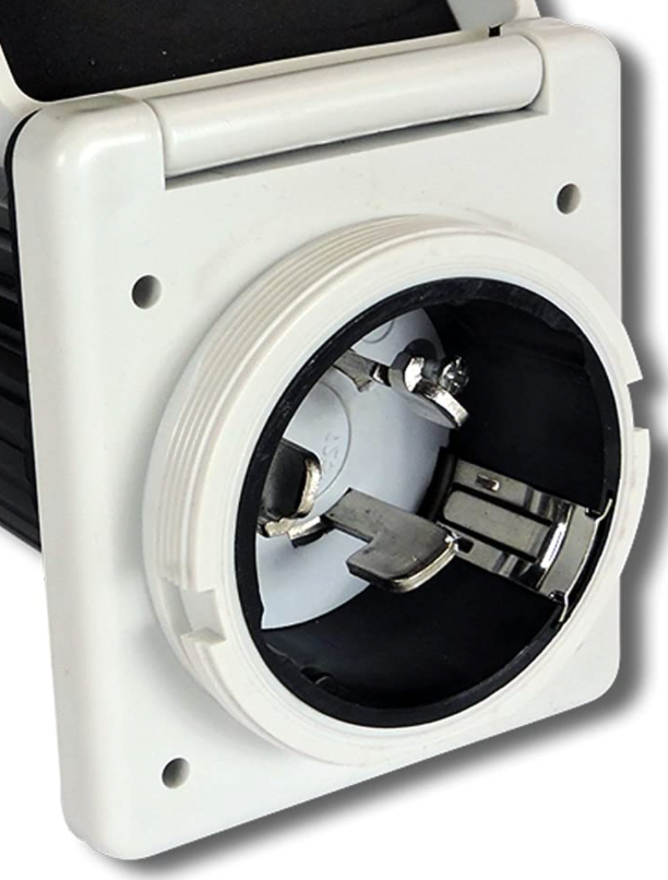
Figure 1 illustrates a typical 50 A shore power connector.
Figure 1 illustrates a typical 50 A RV shore power connector. A power cord may connect this outlet to a shore power pedestal that provides 50 A AC power to run appliances such as air conditioners, microwaves, televisions, and power converters for charging batteries. In addition, a 50 A connector can be adapted to a 30 A or 15 A power source using appropriate converters or dogbones. Alternatively, this connector may be connected to a generator when shore power is unavailable.
The connector illustrated in Figure 1 connects to the RV circuit breaker panel via appropriate conductors inside the RV. For example, our Outdoor RV 240 RKSB has 6/3 Romex that connects the shore power outlet to the main breaker in the circuit breaker panel, as illustrated in Figure 2.
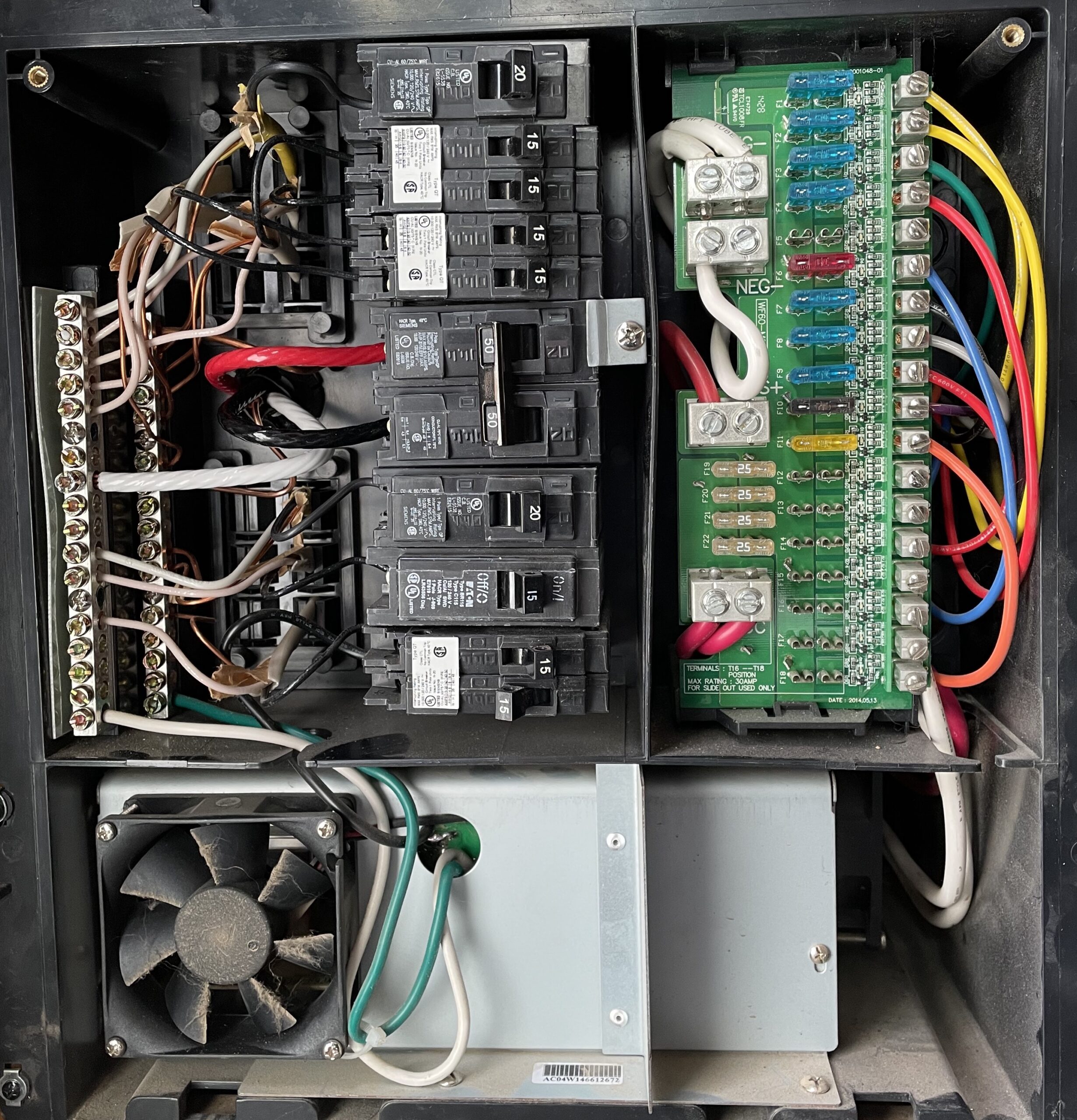
Figure 2 depicts a typical RV circuit breaker panel with a 50 A service.
6/3 Romex has three 6 AWG conductors and one 10 AWG bare copper wire. The 6 AWG red and black wires are connected to the 50 A breaker. The white wire is the associated neutral wire connected to the neutral busbar. The bare copper wire is attached directly to the ground busbar.
The left side of the circuit breaker panel distributes 120 V AC to various trailer components, including 120 V AC outlets, television, microwave, air conditioner, and the power converter located beneath the circuit breaker panel, as illustrated in Figure 2. The power converter converts 120 V AC into the appropriate DC voltages to charge our 12 V RV batteries.
The right side of the circuit breaker panel acquires power from the 12 V RV batteries and distributes this through blade fuses to various RV components such as lights, pull-outs, pumps, USB ports, audio systems, etc. In addition, the power converter output connects to the batteries via this side of the panel for charging.
Inverter/Charger Power
The ability to use all of our 120 V appliances without needing shore power or a generator is the primary objective of this project. Including an inverter/charger in our power center will accomplish this goal. The desired inverter charger will pass through shore or generator power when available and provide 120 V power when they are not. The inverter/charger requires shore power as an input, and its 120 V AC output must be connected to the circuit breaker panel to enable this feature.
We desired to leave the shore power outlet in its original location, requiring us to run 6/3 Romex from the shore power connector to our new power center and another strand of 6/3 Romex from our power center to the circuit breaker panel. Rather than running these two strands to two different locations, we determined to run both from our power center to just behind the circuit breaker panel.
Rather than fussing with the RV underlayment, routing the cables around tanks, and through the frame, we hired this out to Stewart’s RV, our local RV service center. We purchased 125 feet of cable and delivered it to the service folks at Stewart’s, who did an excellent job in all but one aspect. We’ll address the one flaw in the next section.
Figure 3 illustrates conductors of 6/3 Romex spliced using two-conductor Morris connectors.
Once the wiring was in place, we made the right connections. First, we detached the original shore power connection from the circuit breaker panel and spliced it to one of the new 6/3 Romex strands using four two-conductor Morris connectors. These connections are illustrated in Figure 3. Next, we combined the two strands of 6/3 Romex in our power center using four additional Morris connectors. Finally, we joined the remaining conductors to the circuit breaker panel. With these modifications, shore or generator power comes in through the shore power connection, over the original 6/3 wire, through a new strand of 6/3 Romex to our power center, back through the second strand of 6/3 Romex, arriving at the circuit breaker panel. The before and after connections are identical, but the path has increased by roughly 50 feet.
The spliced 6/3 Romex cables in our power center will be separated when our inverter/charger is installed. The 6/3 cable coming from the shore power connector will be tied to the inverter/charger’s input. The remaining cable will be connected to the inverter/charger’s 120 V AC output.
Testing, Debugging, Repairing
Before connecting shore or generator power to our RV, I tested for short circuits within the circuit breaker panel. Unfortunately, I found a low resistance short circuit between the ground and neutral busbar. As a sub-panel, this should not be the case. I looked for obvious wiring flaws but didn’t find any. I returned our trailer to the service center, reporting a short circuit between ground and neutral.
They made a thorough inspection of their work and found no flaws. They did what I should have done after installing the wires and before wiring things together. They tested the continuity between each possible conductor pair of both strands and found no short circuits. I accepted their findings and began a tedious search for the truth. I completely rewired the circuit breaker panel and eventually convinced myself that perhaps it was a strange interaction with the power converter, etc.
I determined to plug the trailer in and see what happens. I knew it wouldn’t be a disaster, but I wanted to see if it would work. Unfortunately, immediately after plugging in the trailer, the GFCI outlet tripped. After much more work, I determined to plug it into a non GFCI protected outlet, and the trailer worked great. I carefully measured the potential between the trailer frame and ground to ensure my safety; everything was fine, well, it seemed fine.
GFCI outlets trip because the current on the hot wires differs from that of the neutral wire by more than 5 mA. In other words, GFCI trips when current is flowing through some undesirable path, like through you. So why was this happening? A considerable amount of literature describes GFCI failures due to long runs, over 100 feet, for example. Essentially, the longer the wire, the more leakage between conductors, and when this exceeds 5 mA, the GFCI trips. Therefore, the longer the wire, the more likely this is. While I had successfully used the failing shore power connection previously, I also recognized that I recently added nearly 50′ to the circuit through my new wiring. Perhaps this was the culprit. I moved the trailer much closer to the outlet and removed more than 50′ of cords, and it still failed.
After disconnecting the cable from the circuit breaker panel and removing the Morris connectors, I rechecked each conductor to ensure independence. Still no short circuits detected. Finally, in a last-ditch effort to find the flaw, I checked each wire in each cable for connectivity to the trailer’s frame. I found the elusive, obvious, and now embarrassing culprit. When the service center installed one of the new cables, its neutral wire was inadvertently electrically connected to the trailer’s frame.
The circuit fails as follows. The ground busbar in the circuit breaker panel is appropriately attached to the trailer’s frame. However, when the faulty neutral wire is connected to the neutral busbar, the trailer’s frame connects the neutral and ground busbars, which is inappropriate for a subpanel.
The test for this condition is simple and easily recreated. I returned the trailer to Stewart’s RV, demonstrated the test described above to them, and they accepted responsibility for the issue. They removed each cable clamp assembly installed, inspected for damage, and repaired where the wire insulation was cut and shorted the neutral wire to the frame. They demonstrated great integrity and excellent service through this ordeal and were consistently friendly and polite. They will get all of my future business.
Summary
Our new AC wiring is in place and works perfectly. One of our goals was to end each sub-project with our trailer in order and available for camping. With this project done and working, we’ve reached that goal. Several takeaways:
Morris connectors are amazingly awesome and much easier to work with than junction boxes.
Vendors, such as Stwart’s RV, with integrity are a pleasure to work with even when things seem tough.
Most importantly, check continuity between each conductor and between each conductor and the trailer’s frame! This one simple test would have saved dozens of hours of searching, poking, disconnecting, etc.
This project was our least understood because of the difficulty and uncertainty of physically dragging cable from the very front to the very back of our RV. However, the rest should be easy with this step done and working. Did I say that out loud?
This post is the fifth of an ongoing series of articles documenting and describing our RV electrical upgrade. Our previous post in this series described creating the physical space for our power center, initial wiring, and solar upgrades. In this post, we describe the Victron Energy Lynx Distributor and a minor modification we made to it to meet our needs better.
Victron Lynx Distributor
Figure 1 illustrates the schematic of our proposed system with a 12 V battery bank.
Figure 1 illustrates the schematic of our power center design using a 12 V battery bank. Our 24 V design is very similar, and the differences are irrelevant to our present discussion regarding the Lynx Distributor shown in the lower center of the figure.
Victron describes the Lynx Distributor as “A modular DC busbar, with locations for four DC fuses. It will monitor the status of each fuse, and indicate its condition with a LED on the front”. The Lynx Distributor is one of four Victron components for power distribution:
Lynx Smart BMS
Lynx Distributor
Lynx Shunt VE.Can
Lynx Power In
See Victron Energy’s website for a complete description of each component with associated datasheets, manuals, certification, etc.
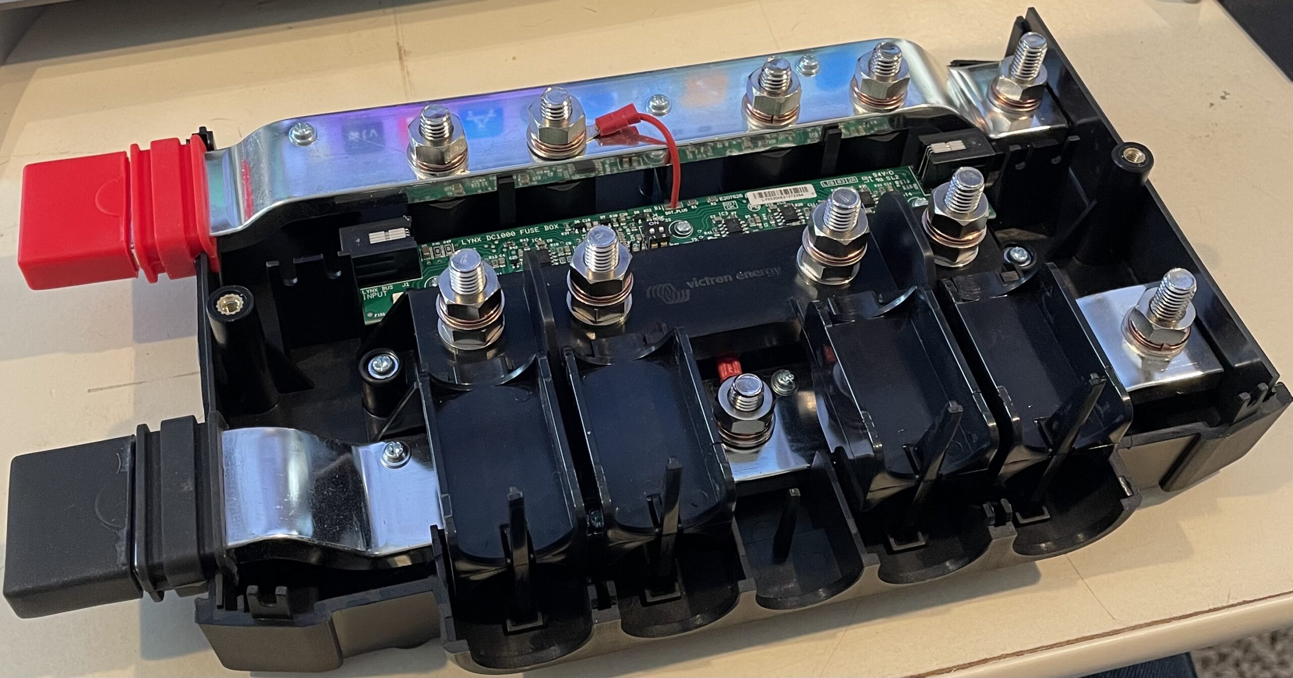
Figure 2 illustrates the internals of a Lynx Distributor comprising a positive and negative 1000 A busbar, four Mega fuse holders, and some electronics that indicate fuse status.
We’ve chosen to use a Lynx Distributor in place of a couple of independent busbars and fuse holders that would otherwise be required. These items are conveniently packaged in the Lynx Distributor, as shown in Figure 2. The cost of separate components is close to the price of the Lynx Distributor, but using the Lynx Distributor should result in a clean, professional-looking result.
Our schematic diagram shows that the Lynx Distributor connects to the battery bank via the disconnect switch and SmartShunt. The Lynx Distributor then distributes power to our inverter/charger, our solar charge controller, and the RV 12 V systems or, in the case of our 24 V design, to a 24 V to 12 V DC to DC converter. Mega fuses, housed within the Lynx Distributor, will protect the wiring between the Lynx Distributor and each of the connected loads.
The Lynx DIstributor can report fuse status via its front panel LEDs if it is connected to a Lynx Smart BMS or a Lynx Shunt VE.Can. We don’t have either of these devices planned for our system. The following section describes how we provided power to the Lynx Distributor circuit board to enable the fuse monitoring feature.
Lynx Distributor Hack
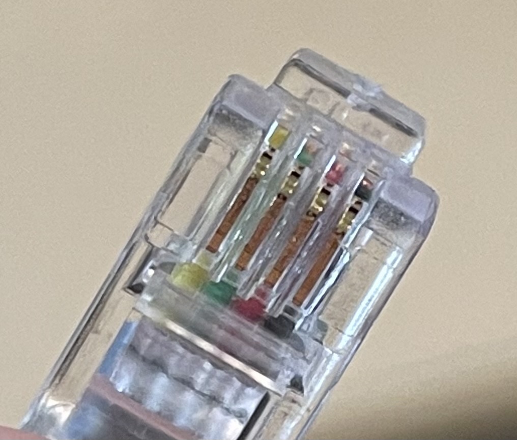
Nate Yarbrough produced a great video describing this hack to enable the lights on the front of a Lynx Distributor without having a Lynx Smart BMS or a Lynx Shunt VE.Can in your system. Victron expects this feature to be enabled by connecting the Lynx Distributor to these other devices with the included cable terminated with RJ-11 jacks. However, the Victron manual for the Lynx Distributor indicates which two of the four lines in the RJ-11 terminated wire are needed to power the device. Victron indicates that the device needs 5 V on pin 1, the yellow wire, and ground on pin 4, the black wire. So the task at hand is to generate 5 V from our available source of either 12 V or 24 V and provide it via an RJ-11 connector.
Fortunately, Victron supplies a cable terminated on both ends with an RJ-11 connector. We cut this cable roughly in half, stripped back the outer covering, cut off the two unneeded wires, and stripped the remaining yellow and black wire in preparation for their connection to a 5 V source.
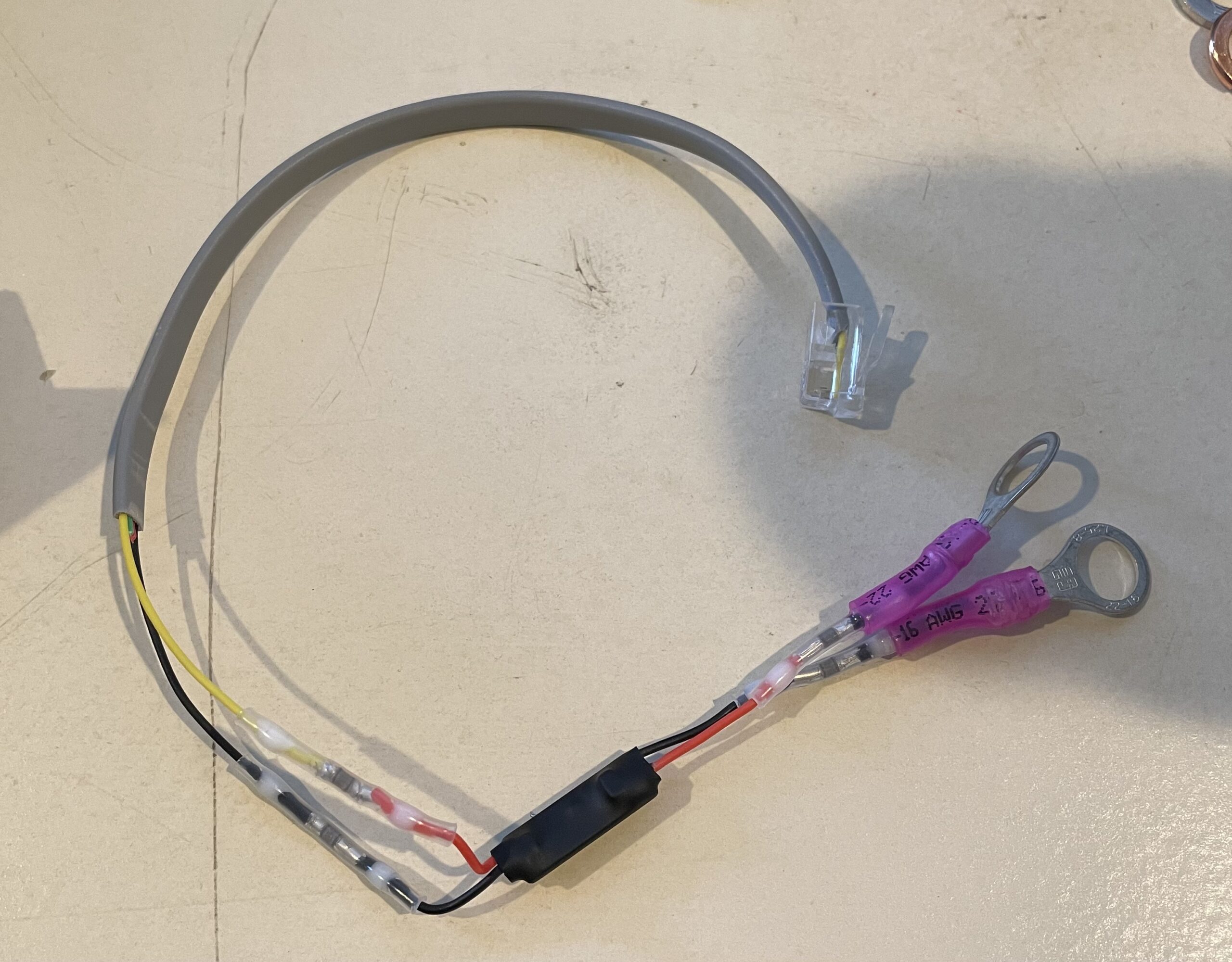
Figure 3 illustrates the small wiring harness, including M8 lugs, an RJ-11 connector, and a 24 V to 5 V regulator.
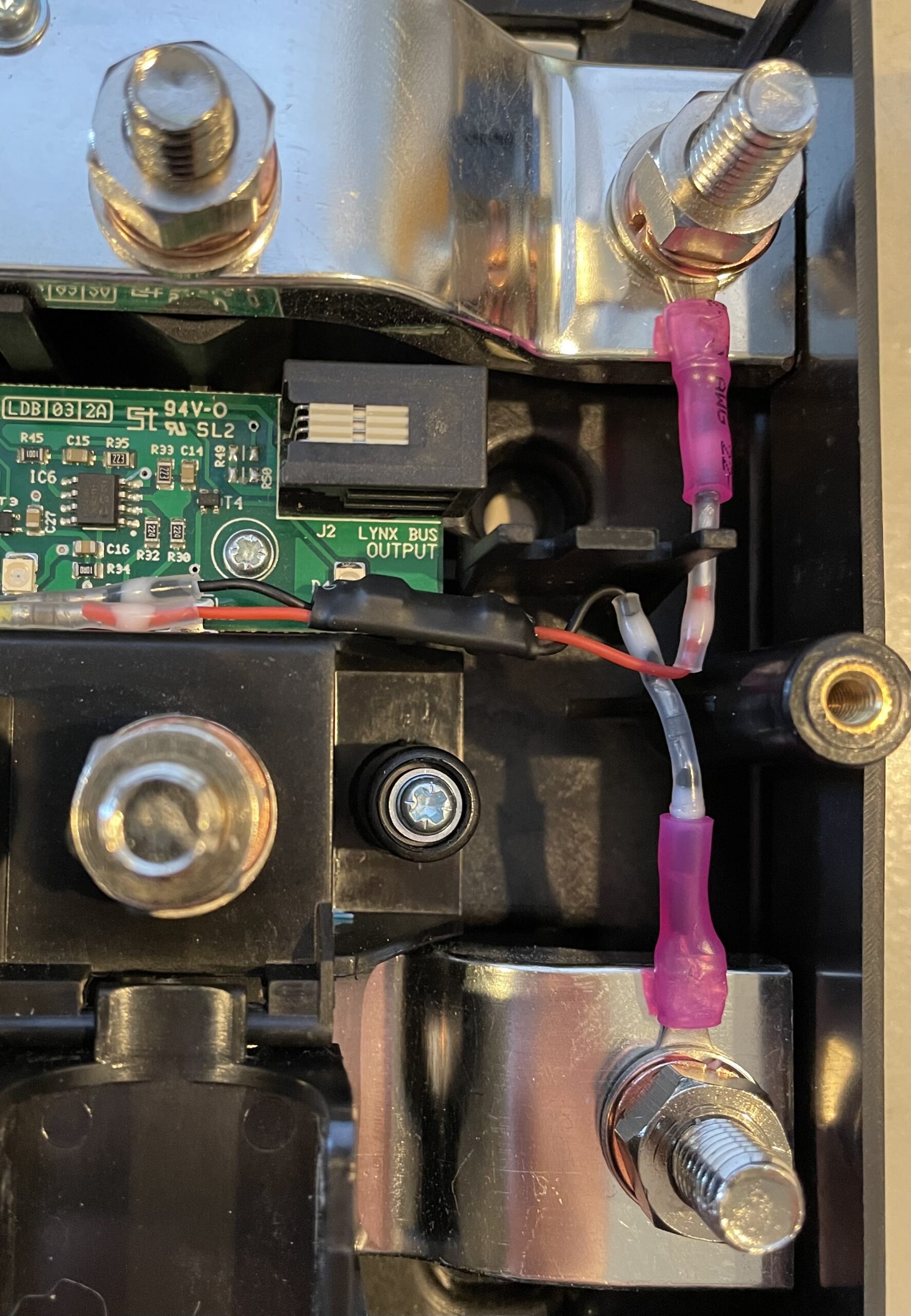
We chose to use a tiny 24 V to 5 V step-down regulator, available here. Four of these devices were approximately $12. They come with wires and connectors attached and covered with heat shrink tubing. It was a simple matter to connect the outputs of this device to the RJ-11 wires and the inputs to two M8 wire lugs, see Figure 3. We then inserted the RJ-11 plug into the Lynx DIstributor and bolted the wire lugs to the busbars where additional Lynx devices could be attached, see Figure 4.
These devices were advertised as 24 V ready, but we wanted to ensure they would handle the voltages in our eventual system. We tested them briefly by applying a voltage source to the Lynx Distributor busbars ranging from approximately 6 V to 30 V. The LEDs continued to function over this entire range. We don’t expect our Lynx Distributor to see voltages outside of this range. If your design operates at 36 V or 48 V, you will need to find an alternative voltage regulator.
Many techniques, devices, and components could be used to accomplish this modification. However, our approach was straightforward. For convenience, we have included a list of the items that we used:
We will use the Victron Lynx Distributor in our power center to yield the functionality of two 1000 A busbars and four Mega fuse holders in an attractive and safe form factor. We discussed a modification to the Lynx Distributor so we can take advantage of the fuse monitoring capability. Finally, we pointed out a few of the devices we used for this project that we have found helpful many times.
This post is the fourth of an ongoing series of articles documenting and describing our RV electrical upgrade. In our previous post, we described our battery bank design and discussed where we would place it. In this post, we describe creating the physical space for our power center, our initial wiring, and our solar upgrades.
Power Center Space
Figure 1, This is a 3D model of the pass-through storage space we intend to use to house our power center.
To house our chosen electrical components, we need to build a space similar to what we previously presented. Our proposed power center is illustrated in Figure 1. Component placement will likely change as we deal with surprises and take advantage of opportunities. However, the basic structure seems sound, and the creation of this space will allow progress.
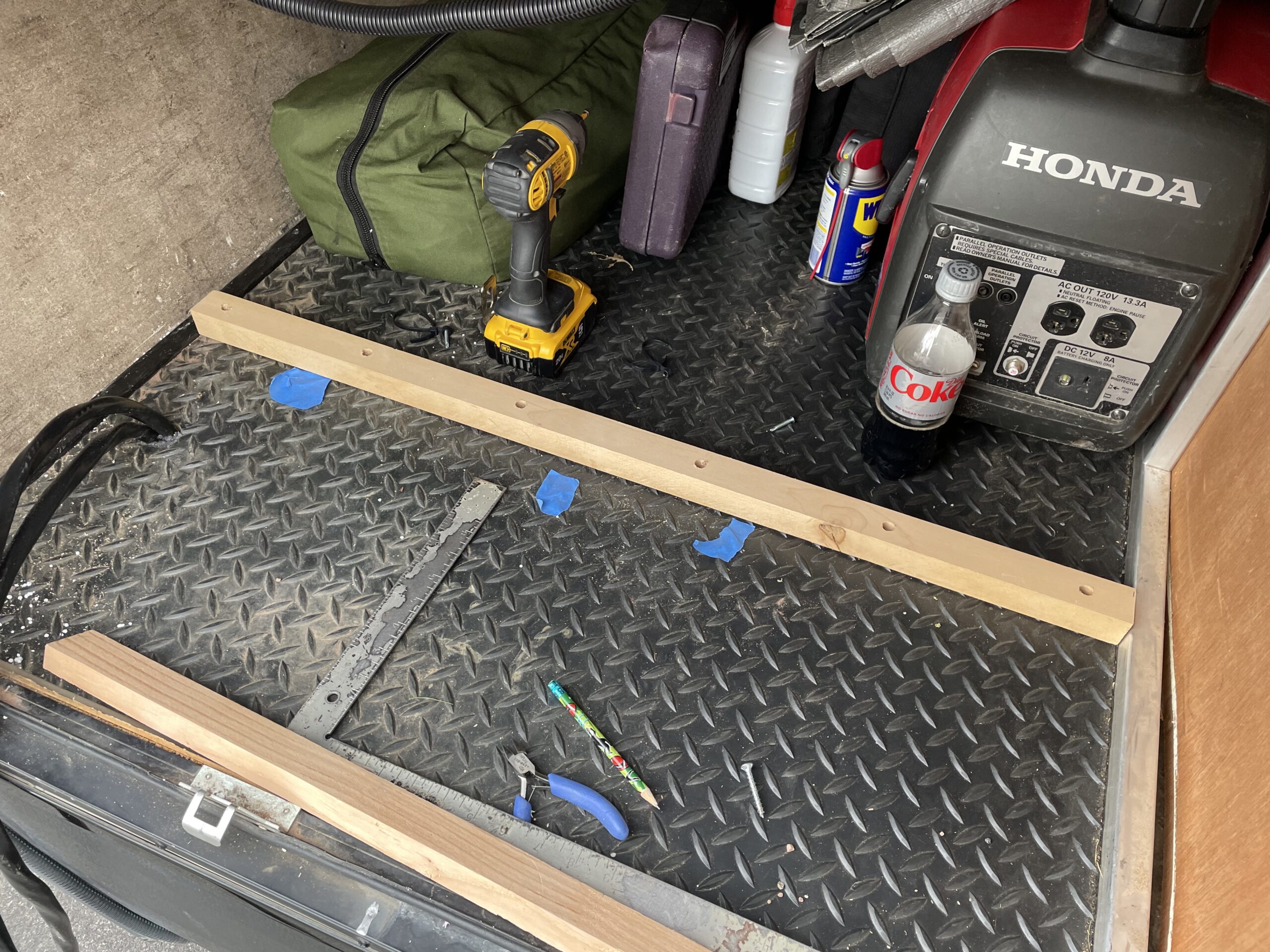
Figure 2 illustrates the physical space we’re starting with and some essential tools, Dewalt impact drill and a Diet Coke. First, we constructed a 3/4″ plywood wall that stretches from the bottom to the top of this compartment and lies flush against the short wall near the top.
Figure 2, This is the space we’re using for our power center. In this picture, we have already run some wires that we’ll describe in the next section.
This approach required a cleat, see Figure 3, attached to the floor to support the plywood wall. To determine the location of the cleat, we held a small piece of plywood against the upper wall and marked the bottom of the compartment with blue tape where it landed when square.
Figure 3, This figure illustrates the lower cleat to support the plywood wall.
The cleat, made of 1-1/4″ by 1-1/4″ lumber, was built by drilling screw holes and countersinking them to allow some 1-1/4″ screws to reach well within the 5/8″ flooring. We also had to add a top cleat, made of the same material, on the right-hand side of this space. The upper cleat was attached to the rectangular aluminum framing using 1-1/4″ self-drilling screws. Finally, before the plywood wall went up, we needed to run a few electrical wires and rescue the Diet Coke.
Initial Wiring
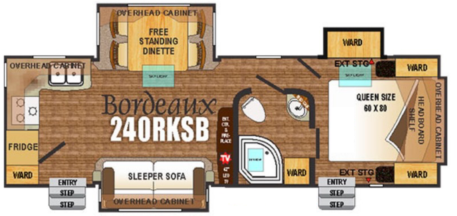
As mentioned in a previous post, our RV is a 2016 Outdoor RV Blackstone 240 RKSB. The floorplan of this model is illustrated in Figure 4. Our new power center will be located in the left-hand side of the pass-through storage area in the upper right-hand corner of Figure 4. Our shore power outlet is located at the left rear of the trailer, while our circuit breaker panel is located just under the refrigerator in the lower left of the figure.
Figure 4, This is the layout of our RV, a 2016 ORV 240 RKSB.
120 Volt AC Wiring
The shore power electrical outlet is wired directly to the circuit breaker panel. However, in our design, the shore power connector must be wired to the inverter/charger, and then the inverter/charger is wired to the circuit breaker panel. We ran Southwire 6/3 Romex from the circuit breaker panel area to the power center to accommodate this need. This line will carry the 50 A shore power to the inverter/charger. We then ran a second piece of 6/3 Romex from the power center back to the circuit panel area. This wire will carry inverter/charger output to the circuit breaker panel to energize our appliances.
Many discussions in RV forums berate Romex because it shouldn’t be used in high vibration environments like RVs and boats. However, Southwire Romex larger than 10 AWG uses stranded wire for three conductors and a solid ground wire. Therefore, we used Romex instead of running a PVC conduit and pulling eight strands of 6 AWG THHN wire through it.
We intended to run this wire ourselves, but it was a task I was not looking forward to. However, our local RV center, where we purchased our trailer several years ago, was willing to run the Romex for a few hundred dollars. That was a deal we couldn’t pass up. They ran the wire neatly and securely and left extra wire coiled behind the circuit breaker panel and in our power center.
Solar PV Wiring
The original solar setup on our trailer was a single 150 W panel on the roof. The installer fed the PV cables through the roof and into an upper cabinet in the bedroom. An inexpensive PWM solar charge controller was installed in that cabinet and then wired down through the trailer cap to the a-frame-mounted batteries.
Soon after purchasing the trailer, we upgraded this setup by replacing the single 150 W panel with three 200 W panels and the PWM controller with an MPPT controller. This upgrade used the existing wiring, and the new controller remained in the bedroom closet. This work aims to improve all aspects of our solar setup and get the solar charge controller out of our cupboard.
We ran new 10 AWG PV cables from the roof through the portal and into the trailer attic near the front of the trailer. Next, we routed the PV cables behind the trailer cap and into our power center. Unfortunately, we purchased 20′ lines with MC4 connectors on each end. We intended to cut the connectors off of one end and fish the cable to its destination. However, we inadvertently cut off the wrong connectors and ended up having to install our own. We should have purchased cable and installed MC4 connectors after they were in place.
Battery and House Wiring
Eventually, as described in our previous post, we will move our battery bank and will need to provide 12 V from our power center to the rest of our trailer. For now, the batteries remain on the a-frame and feed the rest of the trailer from there. Therefore, we need to tap into the existing 12 V and ground line so our new solar charge controller can charge the batteries. Our completed project will eliminate the lines to the batteries.
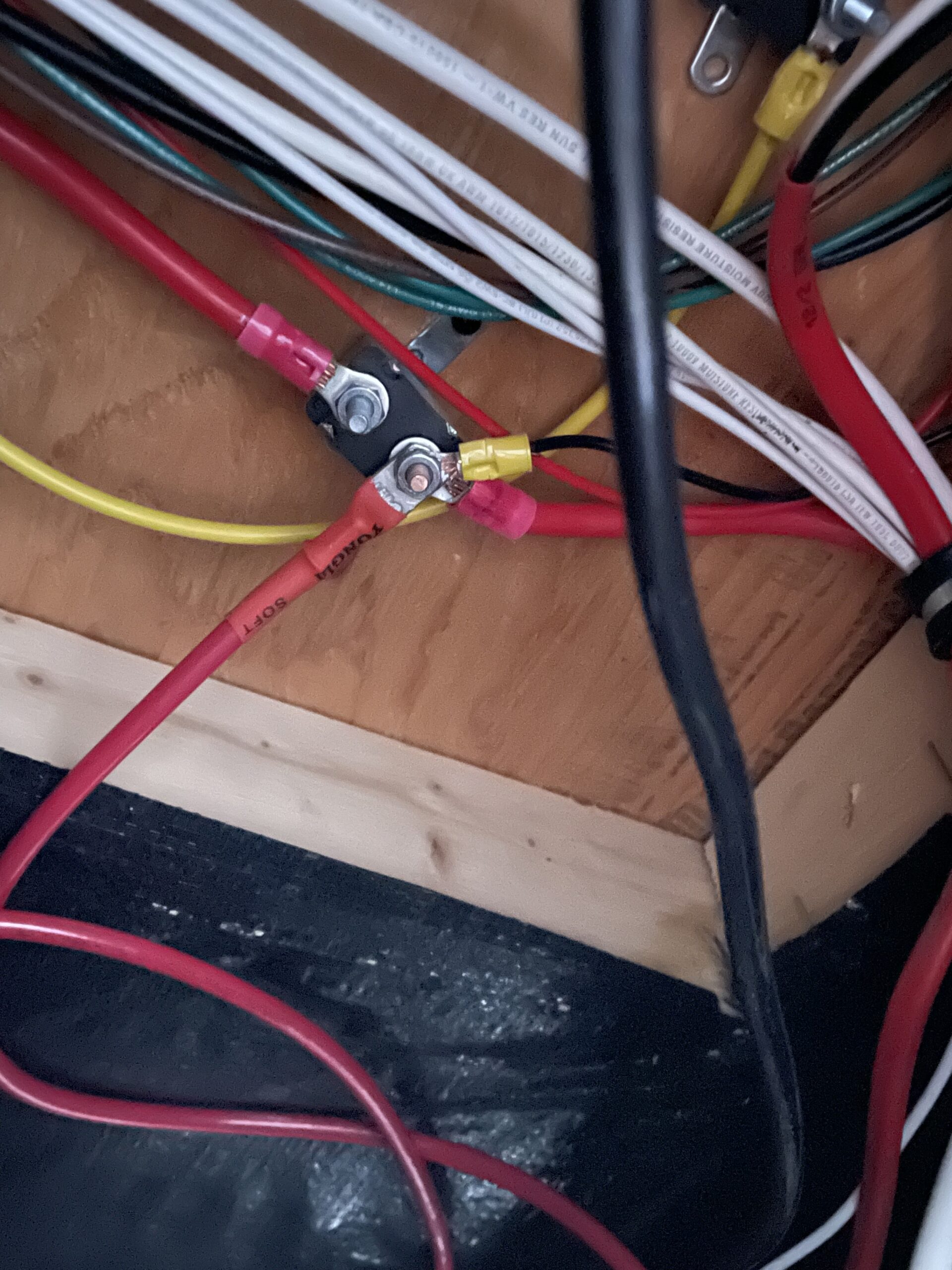
Figure 6, Power and ground distribution travel through this space from the battery bank to the trailer.
On the underside of the subfloor near the a-frame of our trailer, we found several auto reset circuit breakers. The breaker illustrated in Figure 6 has a direct connection to the positive terminal of our batteries. The positive terminal of our batteries and the trailer emergency brake are attached to the shown stud. We attached a 6 AWG THHN wire with a lug to that terminal and fished the wire into our power center.
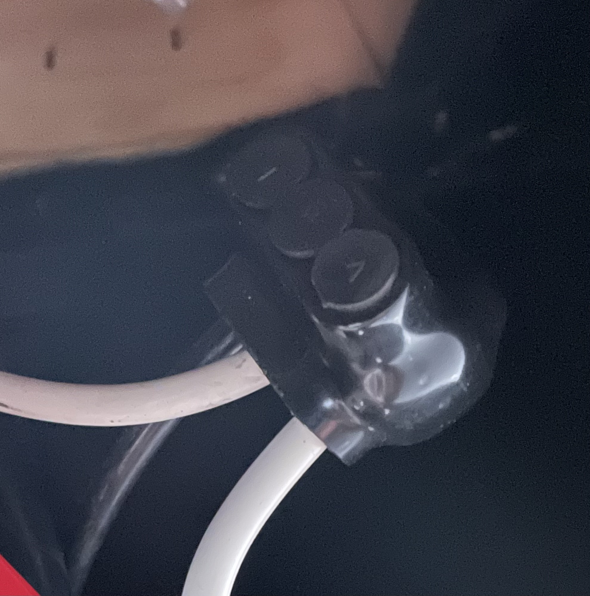
Figure 7, We used a Morris connector to connect a ground wire from the existing ground to our power center.
A ground wire also travels through this area from the negative terminal of our batteries and into the trailer. We obtained ground by cutting the ground wire that travels through this space and connected both ends and a new 6 AWG THHN wire with a 3 position Morris connector, illustrated in Figure 7. These connectors are amazing and easy to use. Finally, we fished the new ground wire into our power center.
After the 120 V AC, solar PV, and 12 V DC wiring were complete, we installed the plywood walls. With this done, the power center is ready for the addition of components. The empty power center can be seen in Figure 8.
Figure 8, The empty power center is illustrated with 120 V AC, 12 V DC, and solar PV wiring in place.
Solar Additions
On the roof of our trailer, we installed a fourth 200 W solar panel, as illustrated in Figure 9. We couldn’t obtain another panel identical to the three we had, so we chose a panel with similar voltage characteristics and a current capability that slightly surpassed our existing panels. This panel will not constrain our system or be significantly limited by our existing panels; it should be a good match.
Figure 9, A fourth 200 W solar panel was added to the roof and connected in series to the existing panels.
Before celebrating the installation of our new panel or our wire routing prowess, we measured a voltage of 60 V across the PV cables. The addition of the fourth panel increased the PV voltage to approximately 80 V; success!
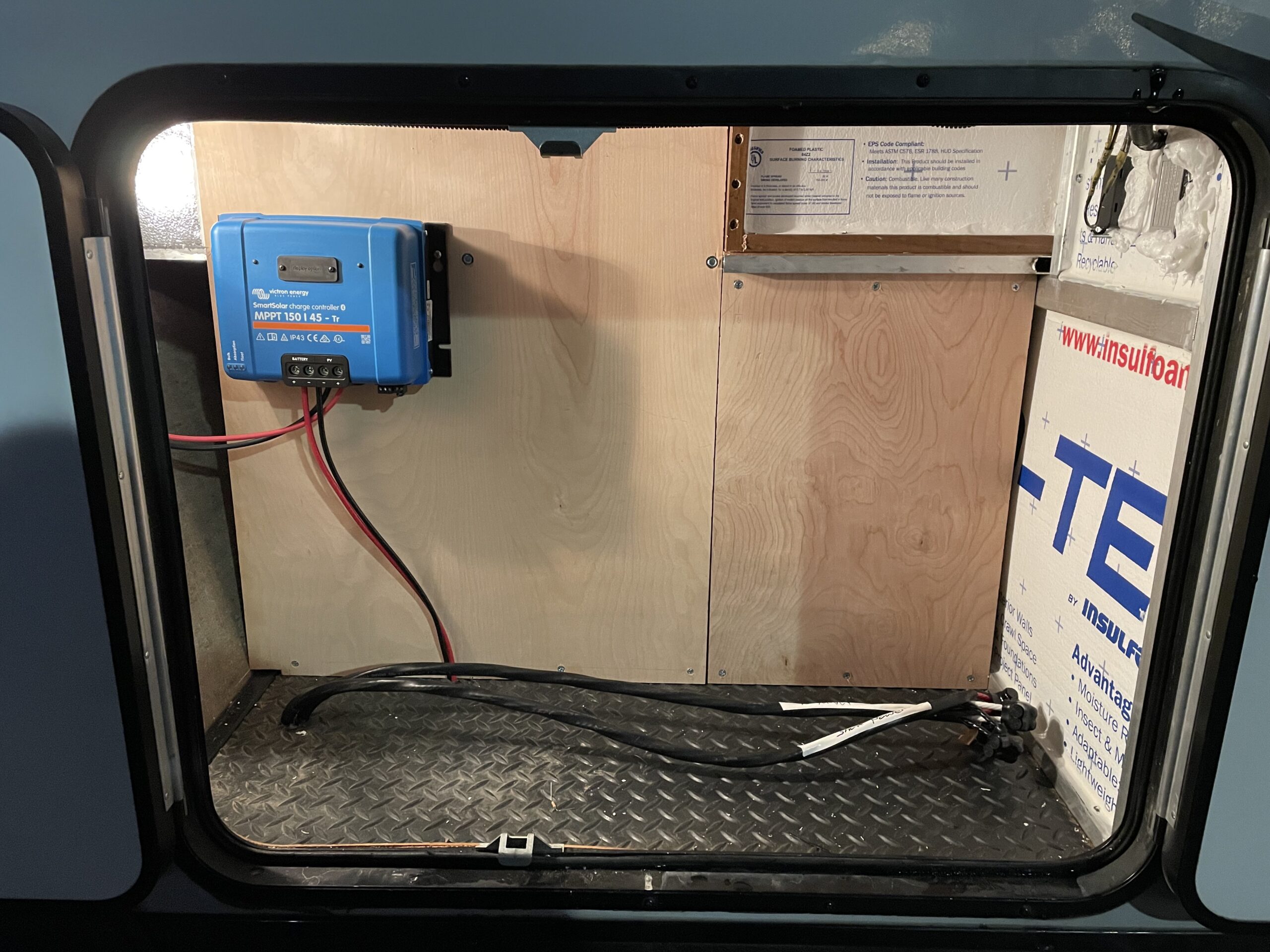
We connected the PV cables to a disconnect switch/circuit breaker mounted in a DIN breaker box in our power center. Next, we used a couple of short lengths of PV cable to run from the breaker box to our Victron SmartSolar 150-45 solar charge controller. Finally, we connected our 12 V DC lines to the solar charger, and we’re back in business. Figure 10 illustrates the result.
Figure 10, The completed power center with solar charge controller and PV disconnect switch installed.
The End Result
We’ve reached the end of another sub-project, and the trailer is once again ready to be used. We successfully created our power center space prepared to receive additional components. In addition, we routed all necessary power cables to this new space. Finally, we added a solar panel and upgraded our MPPT solar charge controller.
This is the third post of an ongoing series of articles documenting and describing our significant RV electrical upgrade. In our previous post, we discussed a potential need for an alternative design and presented its schematic. We also discussed a 3D model of our finished product, and we shared our results. In this post, we describe our battery bank design, discuss where we intend to place it, and the details of making space for it.
Battery Bank Design
Our first article of this series discussed our requirement for a 400 Ah battery bank to meet our electrical needs. However, our 400 Ah requirement assumed a 12 V system. We have since determined that we’d like to implement a 24 V system that reduces our Ah requirement. To enhance clarity, we should discuss our needs in terms of Watt-hours (Wh). A 12 V system capable of delivering 400 Ah is a 4,800 Wh system. A 4,800 Wh 24 V system delivers 200 Ah. We need a battery bank design for both a 12 V and a 24 V system until we determine whether or not Victron will produce a 24 V version of their MultiPlus-II 2x 120V inverter/charger.
Whether we implement a 24 V or 12 V system, we intend to use four Lion Energy UT 1200 lithium-ion batteries to implement our battery bank. We would use their newer UT 1300 batteries, but we already own two of the UT 1200s and found two used UT 1200s for less than half the price of new units. The UT 1200s are rated at 1,152 Wh, while the UT 1300s are rated at 1,344 Wh. So while our goal was 4,800 Wh, we’ll settle for the 4,608 delivered by our four UT 1200s.
24 Volt Battery Bank
We will connect two UT 1200 batteries in series to create a 24 V set. This set can deliver 2,304 Wh, which is well below our goal. Two of these sets can be connected in parallel to yield our desired 24 V battery bank, providing 4,608 Wh. Figure 1 illustrates this configuration. This implementation also adds redundancy in case a battery fails while in the field.
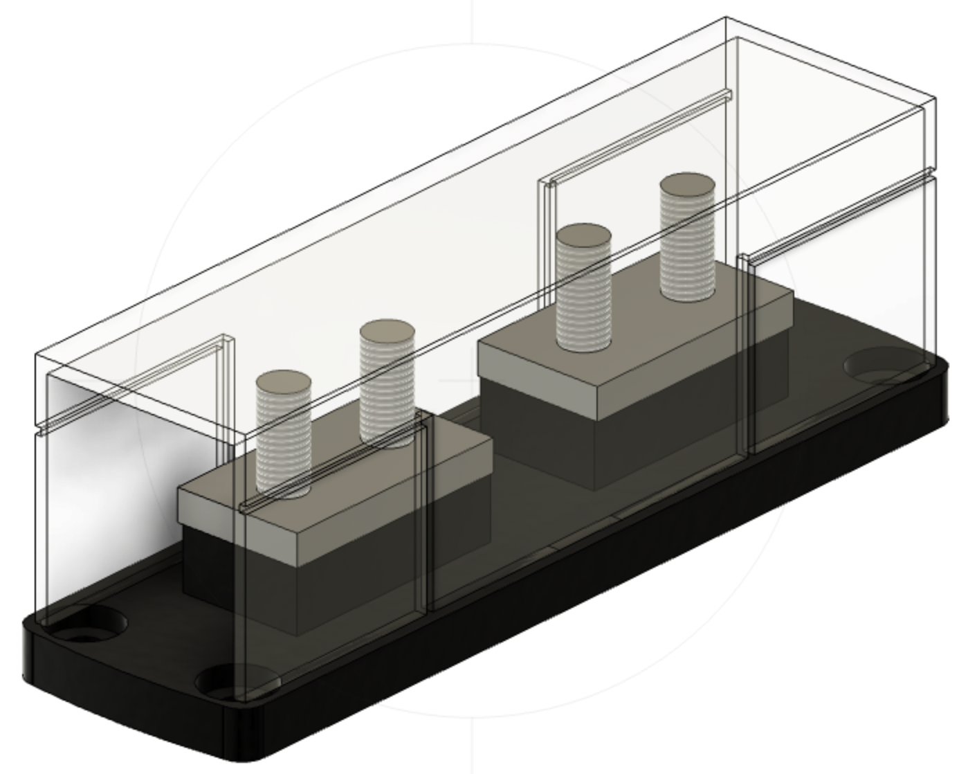
Figure 1, This is a 24 V series-parallel battery bank configuration built using four 12 V Lion Energy UT 1200 batteries. The fuse holder on the left of the figure will hold a 300 A Class T fuse.
Because wire resistance is nonnegligible in these types of systems, it is essential that the circuit length from the positive terminal of any battery, through the load, and back to the negative terminal of the same battery be equal for all batteries in the bank. In practice, this means that the connecting wires between batteries should be of equal length, and the positive and negative connections to the load should be from opposite ends of the battery bank. For example, Figure 1 shows that the positive connection comes from the upper bank, while the negative connection comes from the lower bank.
According to a comprehensive document published by Victron Energy called Wiring Unlimited, an alternative configuration includes a connection between the midpoints of both sets. This configuration is illustrated in Figure 2.
Figure 2, This is a 24 V series-parallel battery bank configuration built using four 12 V Lion Energy UT 1200 batteries and includes a midpoint connection. The fuse holder on the left of the figure will hold a 300 A Class T fuse.
According to the Wiring Unlimited document, this approach requires midpoint monitoring to detect deviations in voltage between the upper and lower batteries. In addition, when deviations are detected and reported, they must be acted on to deal with potential issues. Batteries in the battery bank may be damaged if reported problems are not resolved. Monitoring the midpoint has the advantage of detecting these issues that might otherwise go unnoticed. The Victron SmartShunt, which we intend to use in our system, can monitor midpoint voltages and raise alarms when problems arise.
12 Volt Battery Bank
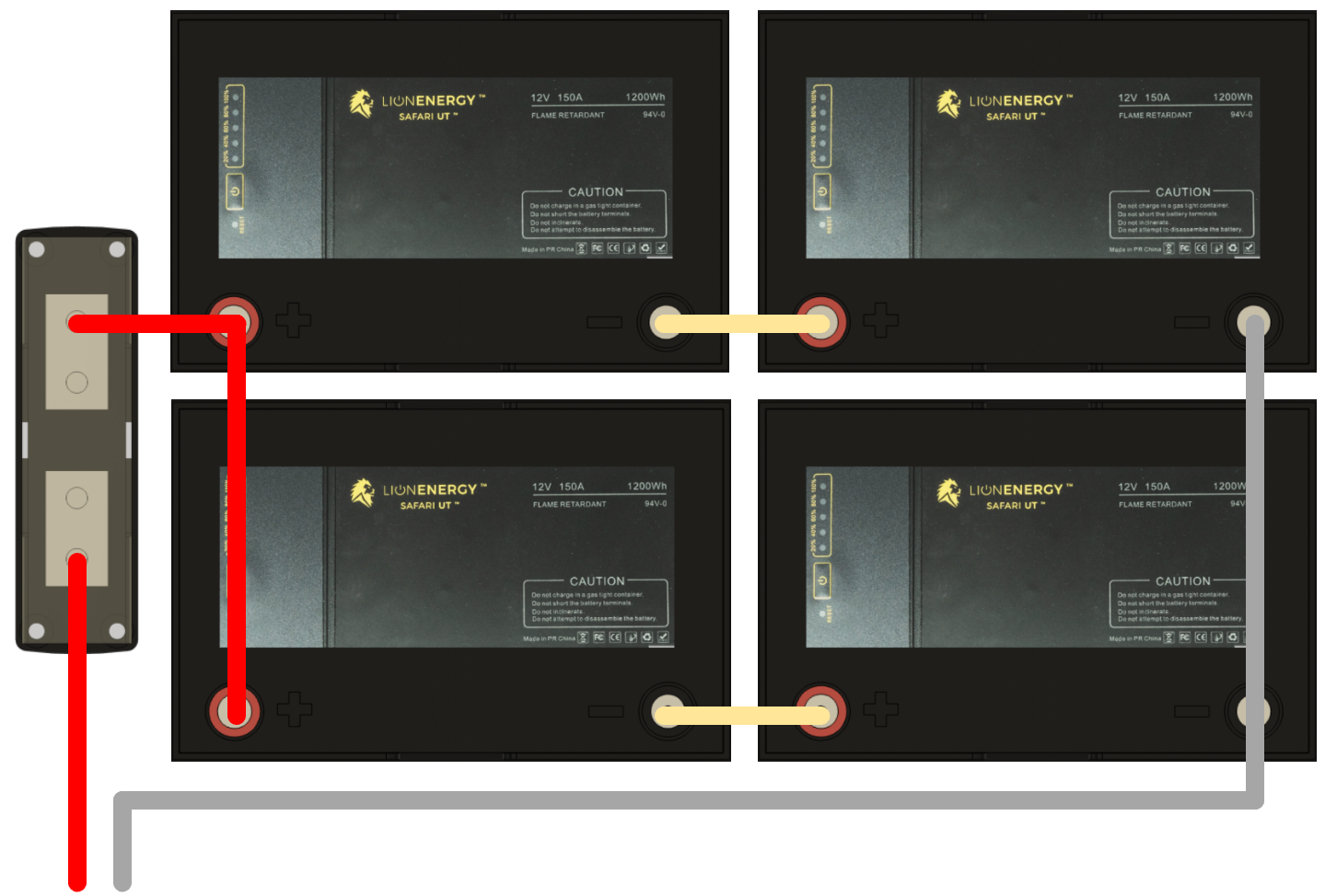
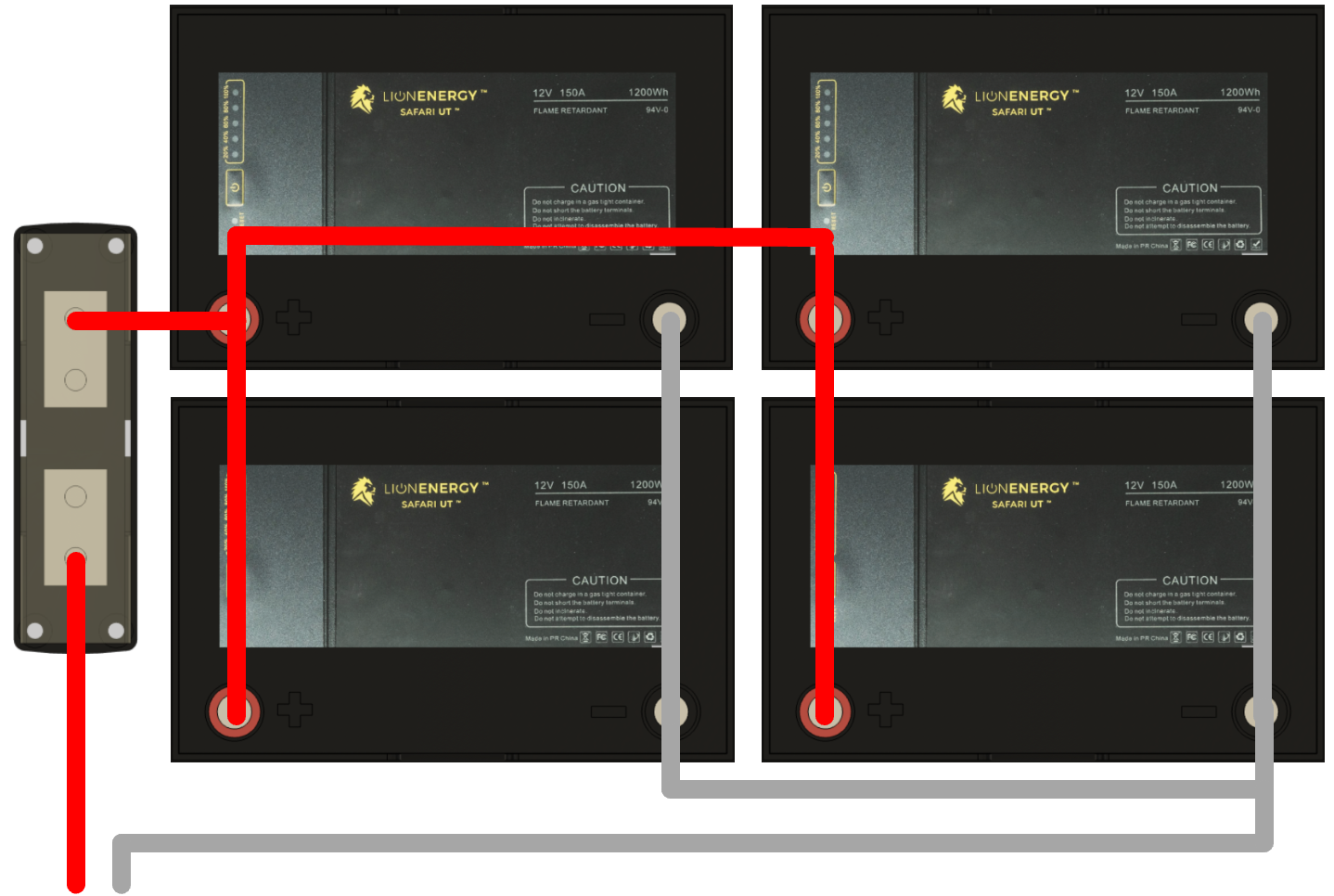
Alternatively, four UT 1200 batteries can be connected in parallel to yield a 12 V battery bank, delivering the same 4,608 Wh. This configuration also adds more redundancy in case a battery fails while in the field. The obvious configuration to accomplish this is shown in Figure 3.
Figure 3, This is a 12 V parallel battery bank configuration built using four 12 V Lion Energy UT 1200 batteries. The fuse holder on the left of the figure will hold a 400 A Class T fuse.
Notice in Figure 3 that the positive connection comes from the upper left battery in the bank, and the negative connection comes from the upper right or the last battery in the bank.
In a 12 V system, the currents are double those of a 24 V system. These higher currents demand a 400 A Class T fuse and wire with double the cross-sectional area of wire used in a similar 24 V system.
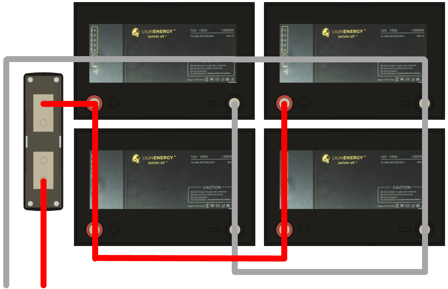
A cleaner wiring layout that still respects the principle of keeping circuit lengths equivalent is illustrated in Figure 4.
Figure 4, This is a 12 V parallel battery bank configuration built using four 12 V Lion Energy UT 1200 batteries. This layout uses the halfway approach of keeping circuit lengths equivalent. The fuse holder on the left of the figure will hold a 400 A Class T fuse.
In the hopes of reducing system currents, voltage drops, and associated ripple, we desire to create a 24 V system. However, if this is impossible due to the lack of availability of an appropriate inverter/charger, the 12 V layout, illustrated in Figure 4, will be used.
Battery Bank Placement
Our RV is a 2016 Outdoor RV Blackstone 240 RKSB. The floorplan of this model is illustrated in Figure 5. Our new Power Center will be located in the left-hand side of the pass-through storage area that is accessed by an exterior door located in the upper right-hand corner of Figure 5. Batteries should be located as close as possible to their associated invert/charger to reduce voltage drops that may occur over long cables. To keep the cables short but still leave storage areas available for their intended purpose, our battery bank will be located under the foot of the bed.
Figure 5, This is the layout of our RV, a 2016 ORV 240 RKSB.
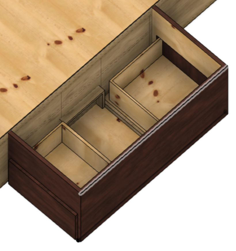
In our last post, we determined that space between the drawers was available for our battery bank. This open space was found during our modeling efforts and is illustrated in Figure 6.
Figure 6, The space between the drawers is sufficient for four Lion Energy UT 1200 batteries.
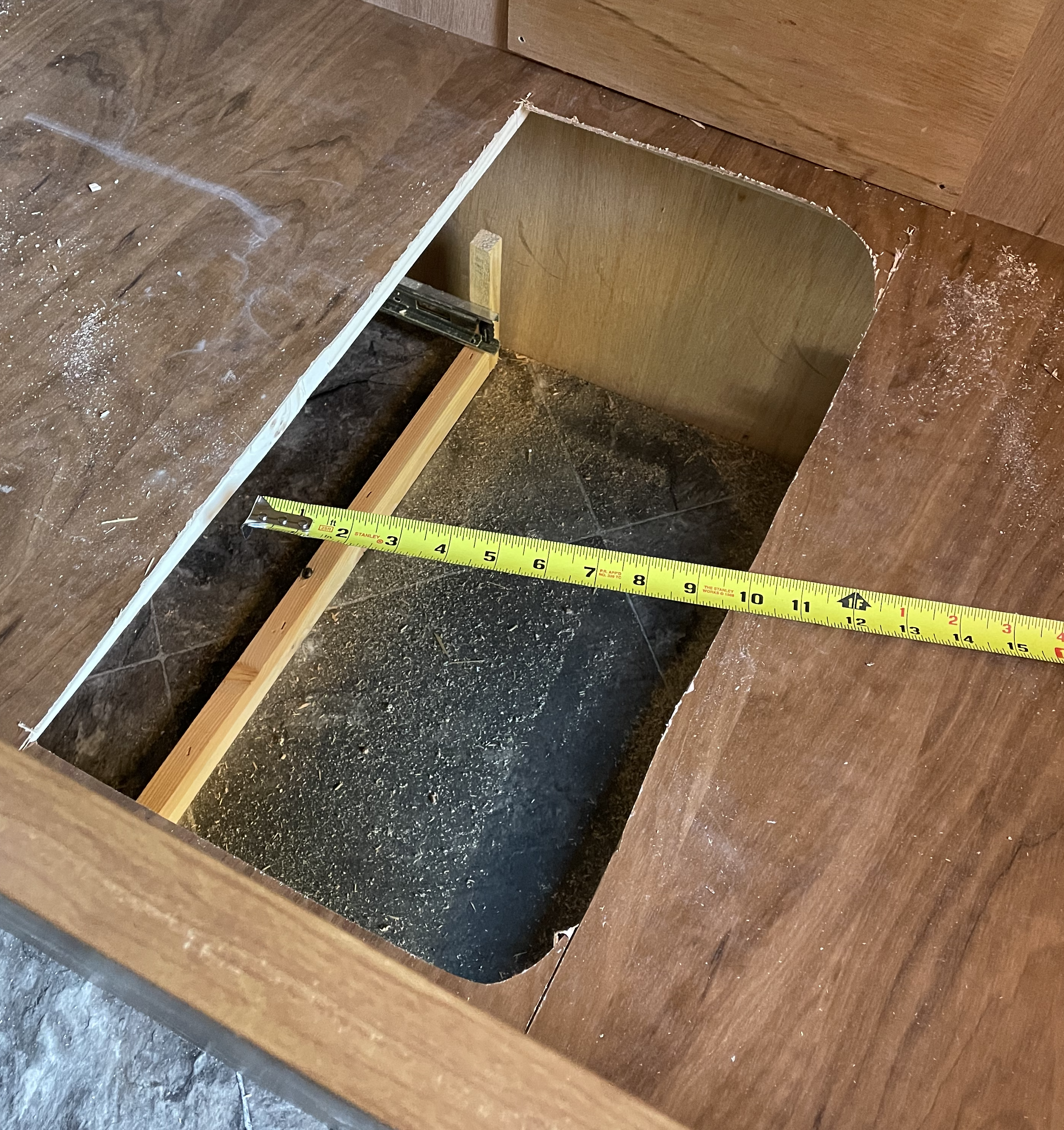
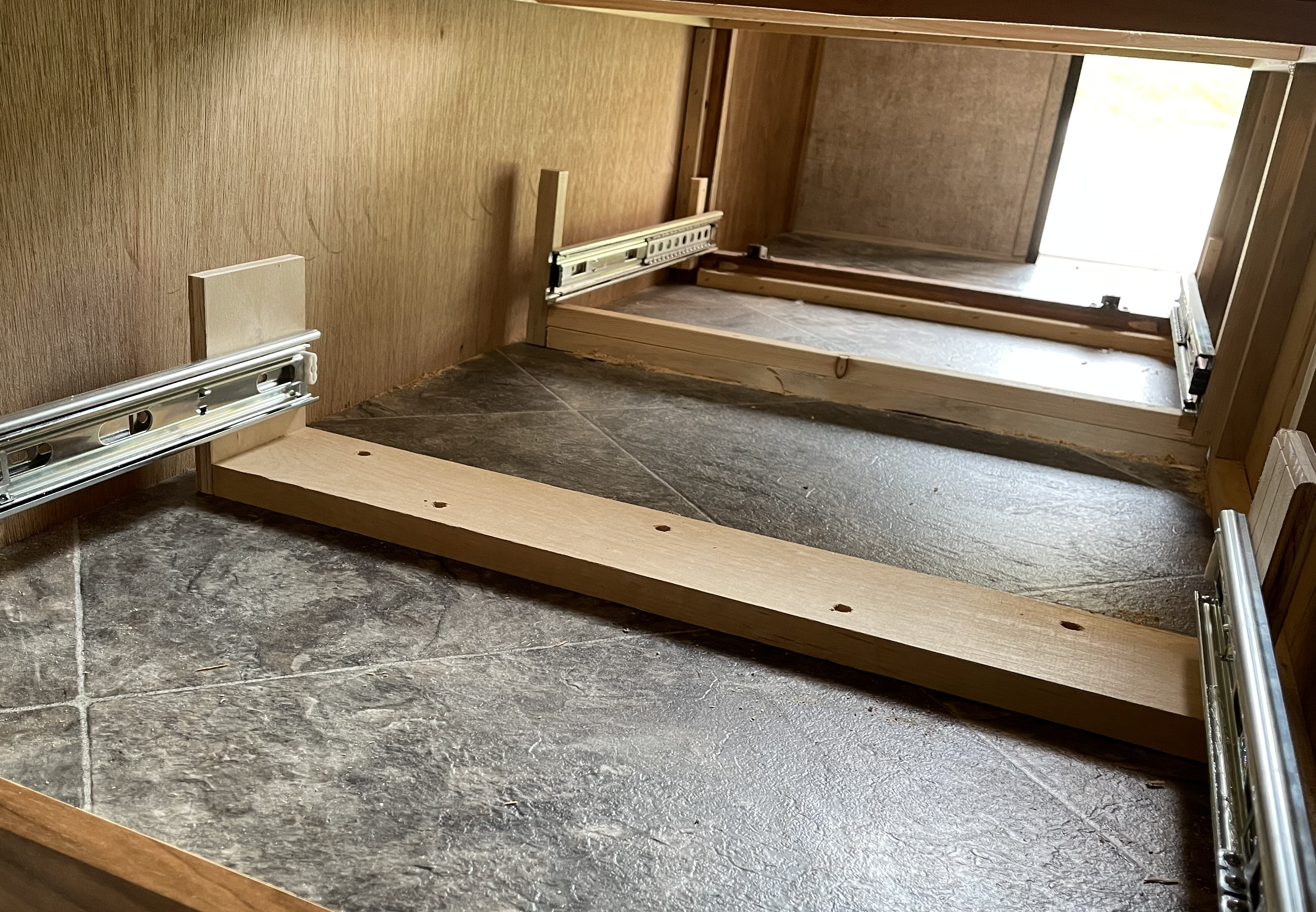
The UT 1200 batteries measure 10.2″ long, 8.8″ tall, and 6.6″ wide. We started demolition to determine the best way to orient these batteries within the available space. We knew from our previous inspections that two cross beams were holding up the false floor of the storage area above the drawers. We removed the drawers and, using a jigsaw, removed the portion of the false floor between the beams. This roughed-out hole and the exposed space are shown in Figure 7.
Figure 7, This is the rough cut opening that exposed the space we intend to use for our battery bank.
While the drawers are only 17″ from front to back, the glides they’re on are 18″ long. The distance between the backs of one set of glides and the other is insufficient for two side-by-side batteries to sit between them. Unfortunately, 17″ drawer glides are unavailable, and the next size down is 16″.
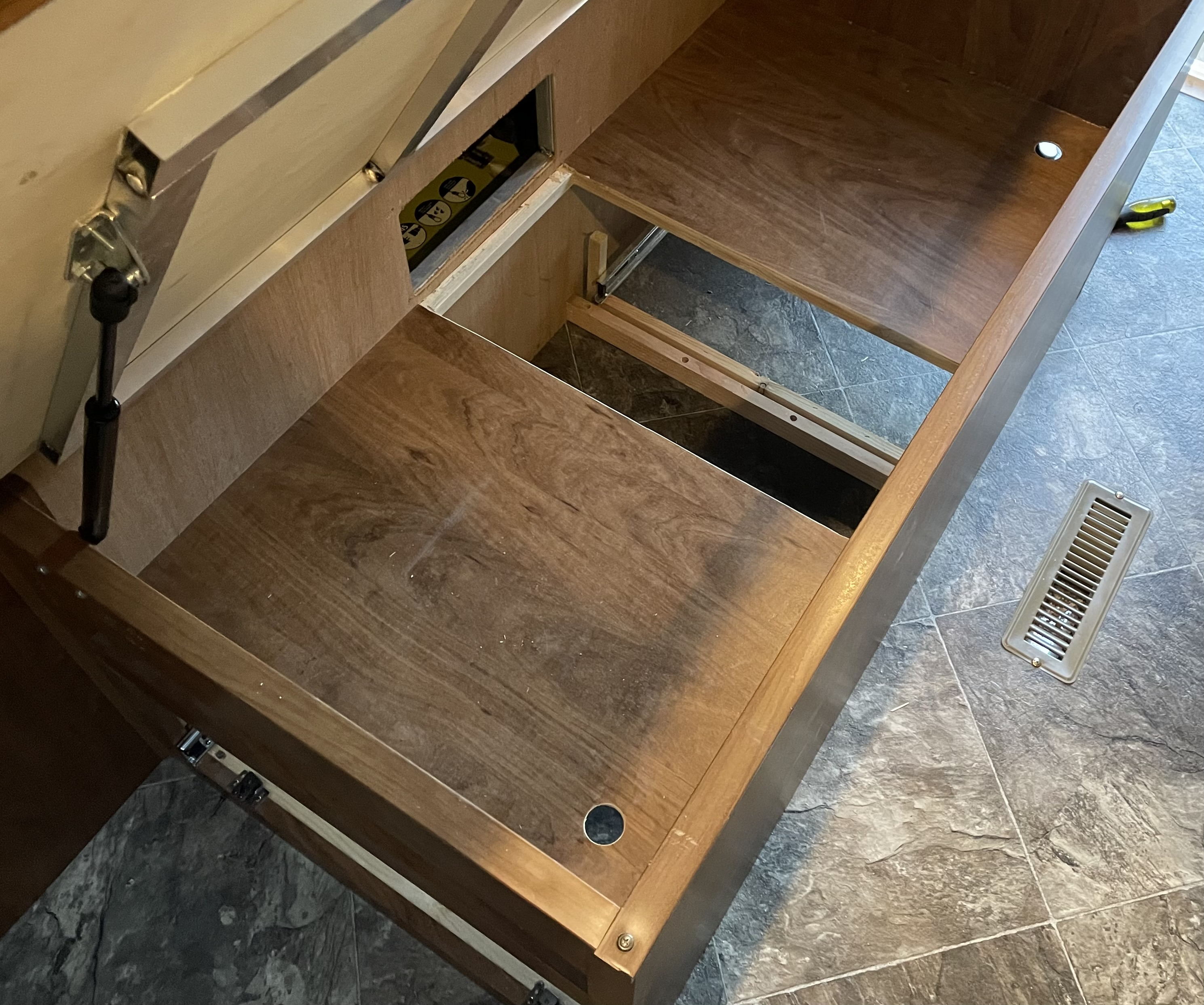
The lack of space necessitated converting one of our drawers to 16″ glides and adjusting the drawer to match. After removing the glide supports and drawer glides, we constructed a new and more robust support structure shown in Figure 8.
Figure 8, This is the drawer space with a new support structure and drawer glides in place.
We acquired and installed new 16″ drawer glides. In addition, we disassembled the associated drawer, cut 1″ off the sides and bottom, and reassembled it better than new.
The remaining space between the backs of both drawers is now more than sufficient to hold two UT 1200’s side by side. The distance from right to left in Figure 8 is also more than enough to hold two UT 1200s longwise. There is also enough space for the fuse holder that needs to be located near the battery bank.
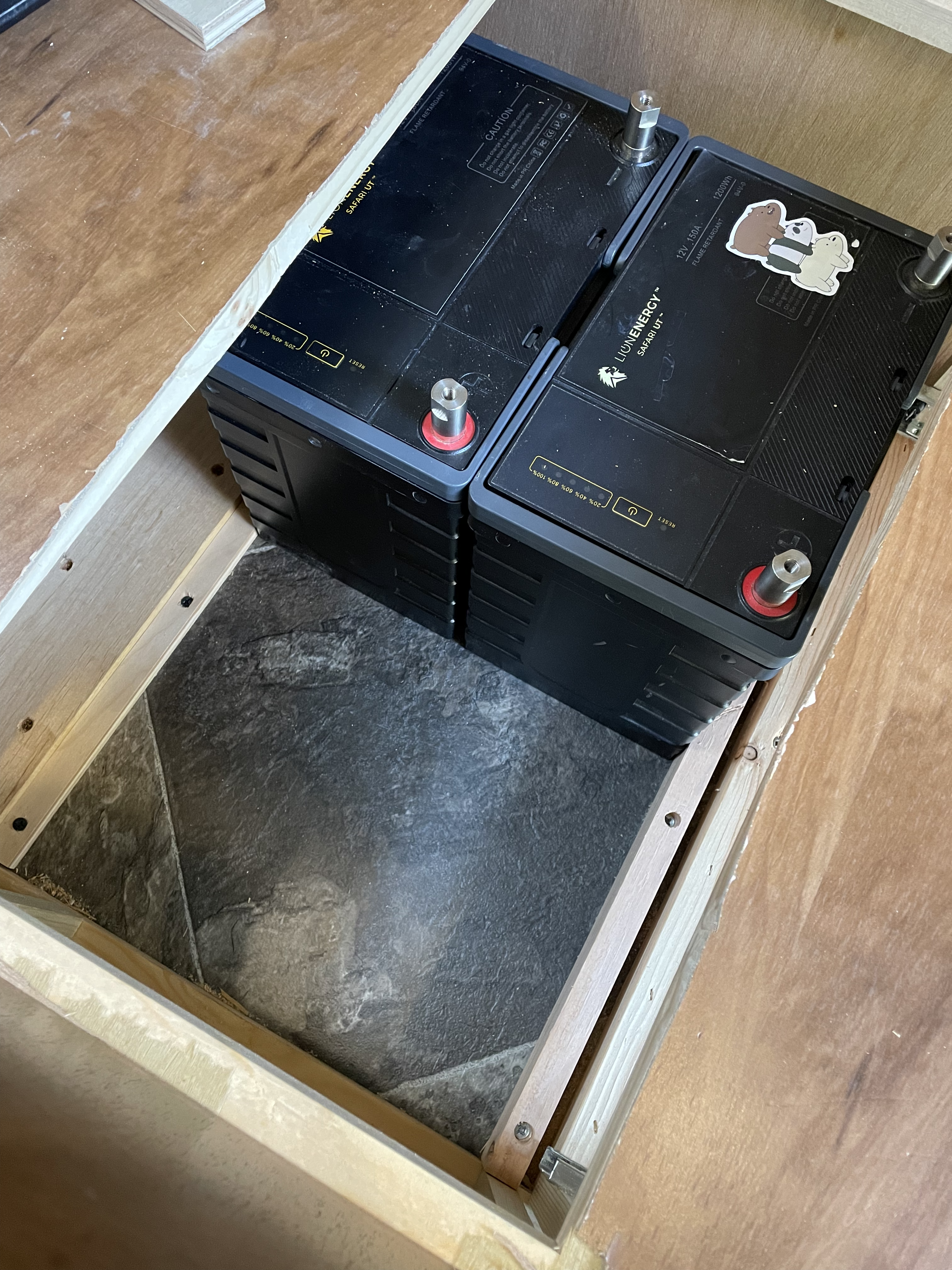
Figure 9 shows the battery bank space with two UT 1200s in place between the installed cleats.
To assist in holding the batteries firmly in place, we added two cleats to the floor spaced to allow the batteries to sit side by side with little to no room to spare. The cleats and batteries can be seen in Figure 9. Also, notice in Figure 9 that the roughed-out access hole has been cleaned up using a round-over bit in our router, some chisel work, and a bit of sanding.
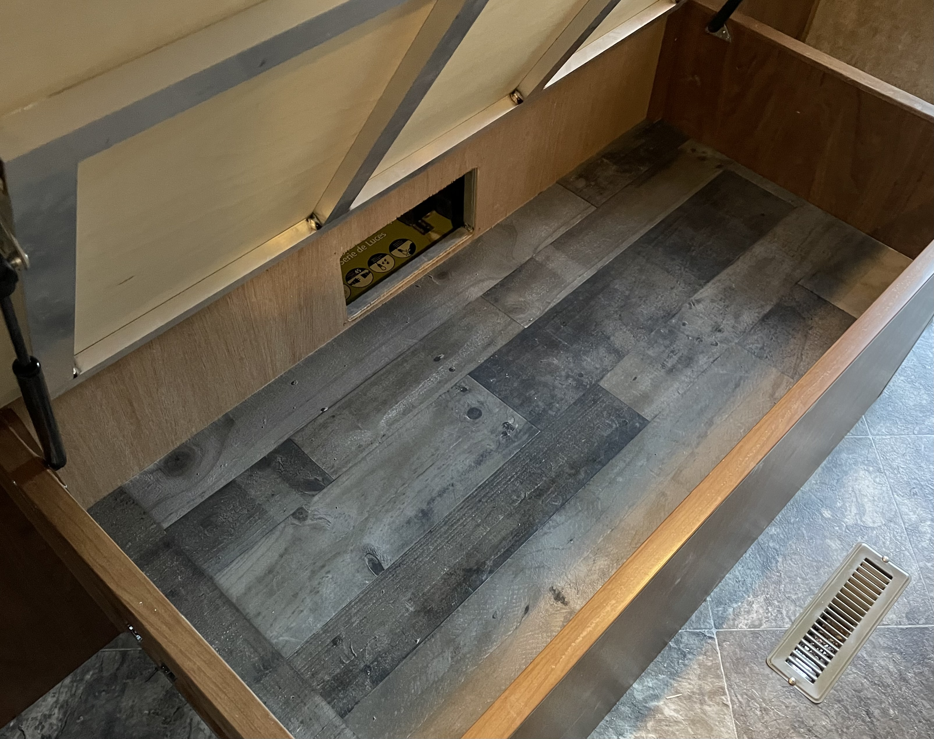
To restore the utility of the storage space used to provide access to the batteries, we drilled finger holes in the remaining false floor. We also added another false bottom over the top of what can be seen in Figure 9. This can be seen in Figures 10 and 11.
Figure 10, Finger holes were added to the existing false floor to facilitate the removal of the new false floor.
Figure 11 shows that the new false floor restores the storage area while protecting the hidden battery bank.
The End Result
In the spirit of making incremental progress and leaving the trailer functional for camping, we’ve reached the end of this sub-project. We successfully created an excellent space for our battery bank that will work for either a 24 V or a 12 V system. The only negative impact of this sub-project was one drawer is now an inch shorter. In future posts, we’ll install the batteries, wire them together, create a small shelf for the fuse holder, and wire the battery bank to the battery disconnect switch and the SmartShunt.
This article is the second of an ongoing series of posts documenting and describing our significant RV electrical upgrade. In our previous post, we outlined our requirements and created a schematic of a system that would meet our needs. We also discussed our desire to do the work incrementally, leaving the trailer in working order after each sub-project. Finally, we discussed our desire to build a 24 V system. In this post, we discuss a potential need for an alternative design and present its schematic. We also discuss the need to model our finished product, and we share our results.
Alternative Design
While we desire to build a 24 V system to reduce currents, Victron Energy does not currently produce a 24 V version of their MultiPlus-II 3000 VA 2x 120 V inverter/charger. However, we are hoping they announce such a device at the METS 2021 conference.
Figure 1 illustrates a schematic for a 12 V system that meets our requirements.
In case a suitable product does not become available, we have designed an alternative 12 V system. This version would not need a 24-12 V DC-DC converter, but increased system currents require larger wires to connect the battery bank to the inverter/charger. Figure 1 illustrates the schematic for our alternative design.
Modeling the System
Our desire to make incremental progress without wasting time or money requires us to see the outcome before taking our first steps. If we don’t know where each component will go and how it will be oriented, we will likely make mistakes that waste resources.
To visualize our project, we used Autodesk’s Fusion 360 3D modeling software to create a model of our RV’s pass-through storage space, our under-bed storage area, and the significant components of our system. Then, by placing the scale versions of the desired components into the modeled spaces, we can arrange and rearrange them to ensure the best overall final implementation. We can then undertake small projects without worrying about them negatively impacting future work. We can also simultaneously work on multiple projects that don’t interfere with one another.
RV Storage Spaces
We initially thought we would put both the power center components and the battery bank in the pass-through storage area. However, we decided to place the battery bank in the under-bed storage to reduce the temperature extremes it would otherwise experience.
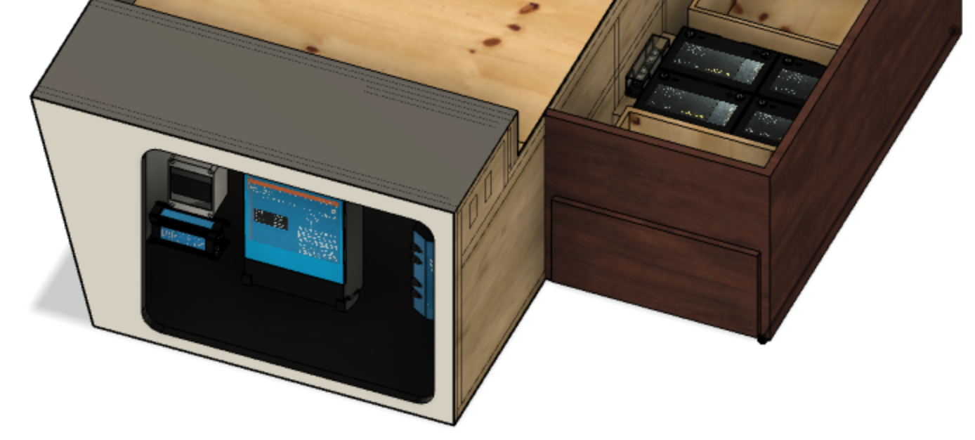
Figure 2, The pass-through storage area, under the bed drawers, and storage space beneath the foot of the bed. Immediately above these modeled objects is where the mattress sits within the trailer.
Figure 3, The pass-through storage area is on the left, and the under-bed storage space is on the right.
Figure 2 illustrates the pass-through and under-bed storage areas of our trailer. It might be helpful to note that the mattress sits immediately on top of these modeled objects. The under-bed storage comprises two drawers, and immediately above them, a small storage space accessible by lifting the foot of the bed. The area illustrated in Figure 3 seemed to be an ideal place for our battery bank.
Figure 4, The space between the drawers is sufficient for four Lion Energy UT 1200 batteries.
However, we discovered some completely wasted space between the two drawers during our modeling efforts, see Figure 4. This space is almost large enough for four Lion Energy UT 1200 batteries. Some modifications will be necessary, but using this space will leave both the under-bed and pass-through storage areas free for their intended purposes.
This example points out the sound practice of measuring things out and opening up places in your RV to determine what is there and what’s available. You never know when you may need a bit of space for one thing or another.
Modeled Components
Modeling the trailer spaces gave us a great reason to learn a bit about Fusion 360. While we aren’t experts, we learned enough to model each of the major components we’ll use in our system. These models are not precise, but their overall dimensions and appearance are accurate enough for our purposes.
This modeling effort enabled us to place each component, move them around, ensure adequate spacing, etc. The implementation illustrated in Figures 5 and 6 was achieved by adding a wall in our pass-through storage space and placing the modeled components. As previously mentioned, we may have to implement a 12 V alternative by removing the DC-DC converter and adjusting fuse values appropriately.
Figure 5, This is the front view of the RV Power Center showing the layout of all major components. The solar charge controller and PV breaker are in the upper left. The DC-DC converter is in the lower left. The inverter/charger is in the center of the figure, while on the right side, we have from top to bottom the Cerbo GX monitoring system, the SmartShunt, battery disconnect switch, and the Lynx Distributor.
Figure 6, This top view of the RV Power Center component layout demonstrates sufficient clearance from all devices, walls, doors, etc.
Figure 7, The four batteries fit nicely between the drawers with the 300 A Class T fuse nearby.
As previously mentioned, the battery bank will be located between the drawers in the under-bed storage area. In addition, we’ll build a small shelf near the batteries where our 300 A Class T fuse will be located. The battery cables will pass through the thin wall between the under-bed area and the pass-through storage area and then travel down to the left in Figure 7 until they reach the battery switch and SmartShunt.
Summary
In this post, we discussed our alternative 12 V design and modeled the physical spaces and components in the hope that we get it all right the first time around. This may be an optimistic goal, but having this detailed plan in hand will enable small projects to fit more seamlessly together. Now the work begins.
We spent more than 30 years tent camping and backpacking with our children, but recently we’ve transitioned to a bumper pull RV. We continue to love camping in the great outdoors but like to do so with all of the luxuries of life, glamping. We love the solitude and the noises of nature and tolerate crowded campgrounds and the noise of generators that start each morning and run through the day. Instead, we want to take a different path. We want the best of both worlds, and this series of posts will document our path that leads there.
The Big Picture
We want the ability to use our microwave, television, and other 120 V AC systems without having to ruin our camping solitude with a generator. In addition, we want to minimize the intrusion of our generator while recharging our batteries.
On a typical day of camping in our RV, we consume 1400 Watt-hours or approximately 115 Ah of our 12 V system. About 30 Ah are consumed watching television for a few hours and 85 Ah for lights, fans, heater blower, etc. We want to watch TV for several hours per day and use a game console for several additional hours. In addition, we want to use our microwave for making snacks along the way.
Using our TV for six hours consumes 60 Ah, three hours of our game console consumes 30 Ah, and our microwave for 10 minutes consumes 13 Ah, totaling 103 Ah. This usage, combined with the 85 Ah mentioned above, brings the total to nearly 200 Ah. To ensure some reserve power, we’re planning on a 400 Ah battery bank. To recharge our batteries each day, without having to hear that noisy generator, we’re planning on 800 Watts of solar.
To accommodate our AC devices, including the TV, game console, and microwave, we need an inverter/charger capable of producing 1320 Watts or more. We’d also like to use our air conditioner for short periods to keep our dog comfortable while we shop, eat in a restaurant, take a short hike, etc. Our air conditioner consumes approximately 1500 Watts. We also desire the charger to charge our battery bank as quickly as possible for those terrible days when we have to run our generator. Our RV is wired for a 50 A service, and this should be passed through to the circuit panel when connected to shore power.
In summary, we want to enjoy the quiet solitude of camping and some of the luxuries of life. We want to do this with as few detrimental modifications to our trailer as possible. Several items will make this goal a reality:
400 Ah of lithium-ion batteries
800 Watts of solar power
An inverter that is capable of producing nearly 3000 Watts of 120 V AC power
A battery charger that is capable of consuming our entire generator output to minimize charge time
Our Plan
We intend to accomplish our previously outlined goals incrementally so that between projects, our trailer is still functional. Therefore, our first step was to develop our design so we could start breaking it into sub-projects. Figure 1 is the schematic of the plan we intend to implement.
We made an early design choice to create a 24 V system with four 12 V lithium-ion batteries. We chose this because the components we intend to use work at 12 or 24 V, and at 24 V, the system currents will be cut in half, reducing wire size and decreasing unwanted heat dissipation.
Figure 1, Schematic diagram of 24 Volt electrical system with 12 Volts available for backward compatibility with existing RV systems.
We intend to locate most of the equipment illustrated in Figure 1 in the left-hand side of our pass-through storage area near the front of our trailer. We’re going to call this location our power center. The solar panels will go on the RV roof, and the batteries are going under our bed which is just to the rear of the pass-through storage area.
Currently, our trailer is configured in a fairly standard way. We have two Lion Energy UT 1200 lithium-ion batteries mounted on the front a-frame of our trailer and housed in conventional plastic battery boxes. We have some solar on the roof with the solar charge controller mounted in a bedroom closet, and the rest of the electrical components and wiring are factory default. Our upgrade project will require a lot of time and work, and as previously mentioned, we intend to do it incrementally and leave our trailer in shape for traveling between sub-projects. Our tasks include:
Constructing the new power center with sufficient space and strength to mount all of the components in our design.
Adding solar panels, routing PV cables to our new power center, mounting our charge controller and disconnect switch, and connecting to our original battery bank.
Making room for our four batteries under our bed.
Connecting the batteries in a parallel/series configuration to obtain our desired 24 Volt system and interfacing this new battery bank to the existing RV systems.
Routing AC lines from the power center to the existing RC circuit panel and back.
Mounting the remaining components in the power center and wiring them into the system.
Configuring each prgrammable component.
Thoroughly testing the system, cleaning up flaws, and enjoying the outcome
This post is the first in a series to document our journey from where we are to where we want to be. Each sub-project above will be thoroughly described in separate posts, and we’ll include the good, the bad, and the ugly. We hope you enjoy our journey.