This post is the fourth of an ongoing series of articles documenting and describing our RV electrical upgrade. In our previous post, we described our battery bank design and discussed where we would place it. In this post, we describe creating the physical space for our power center, our initial wiring, and our solar upgrades.
Power Center Space
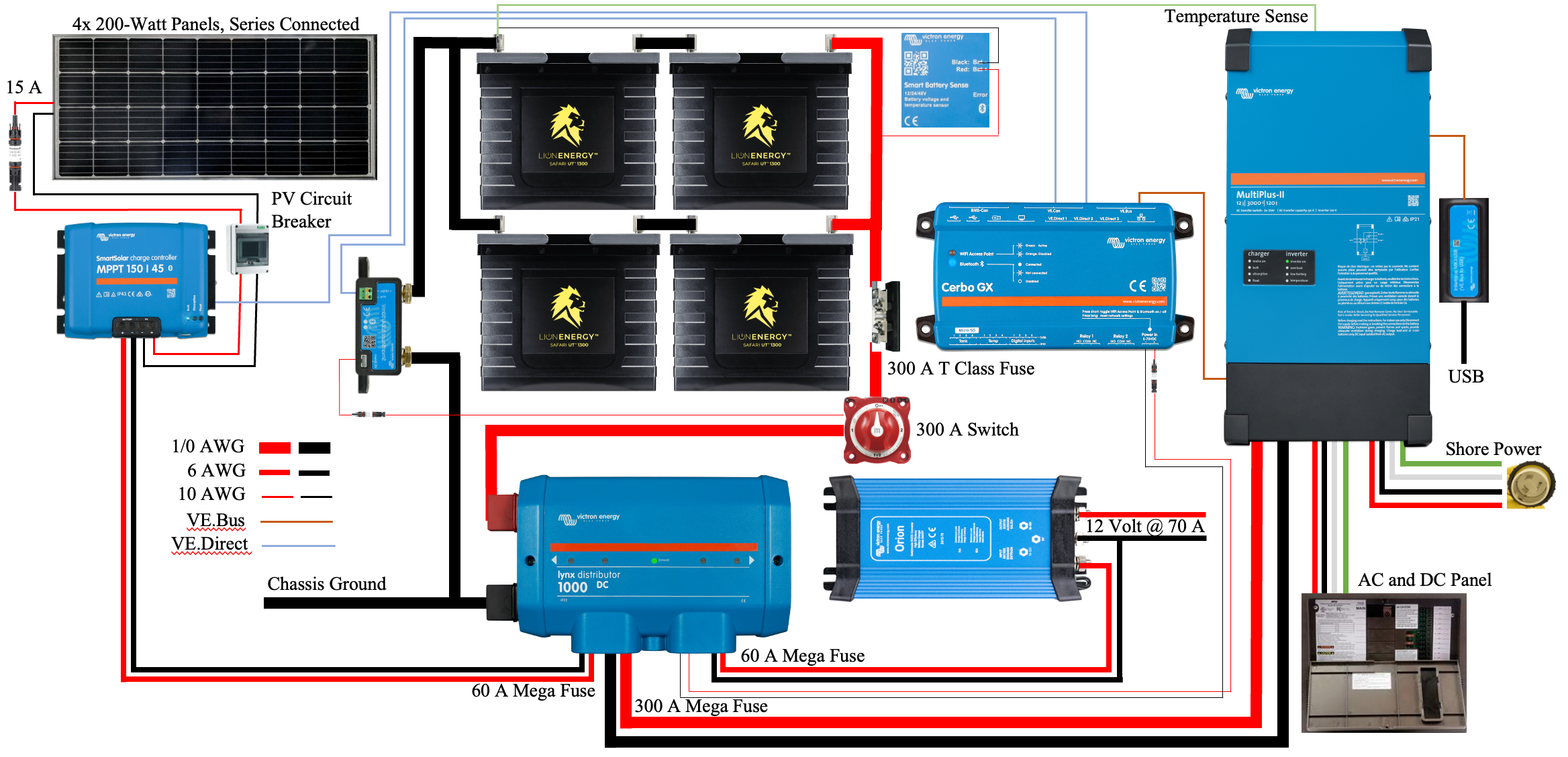
To house our chosen electrical components, we need to build a space similar to what we previously presented. Our proposed power center is illustrated in Figure 1. Component placement will likely change as we deal with surprises and take advantage of opportunities. However, the basic structure seems sound, and the creation of this space will allow progress.
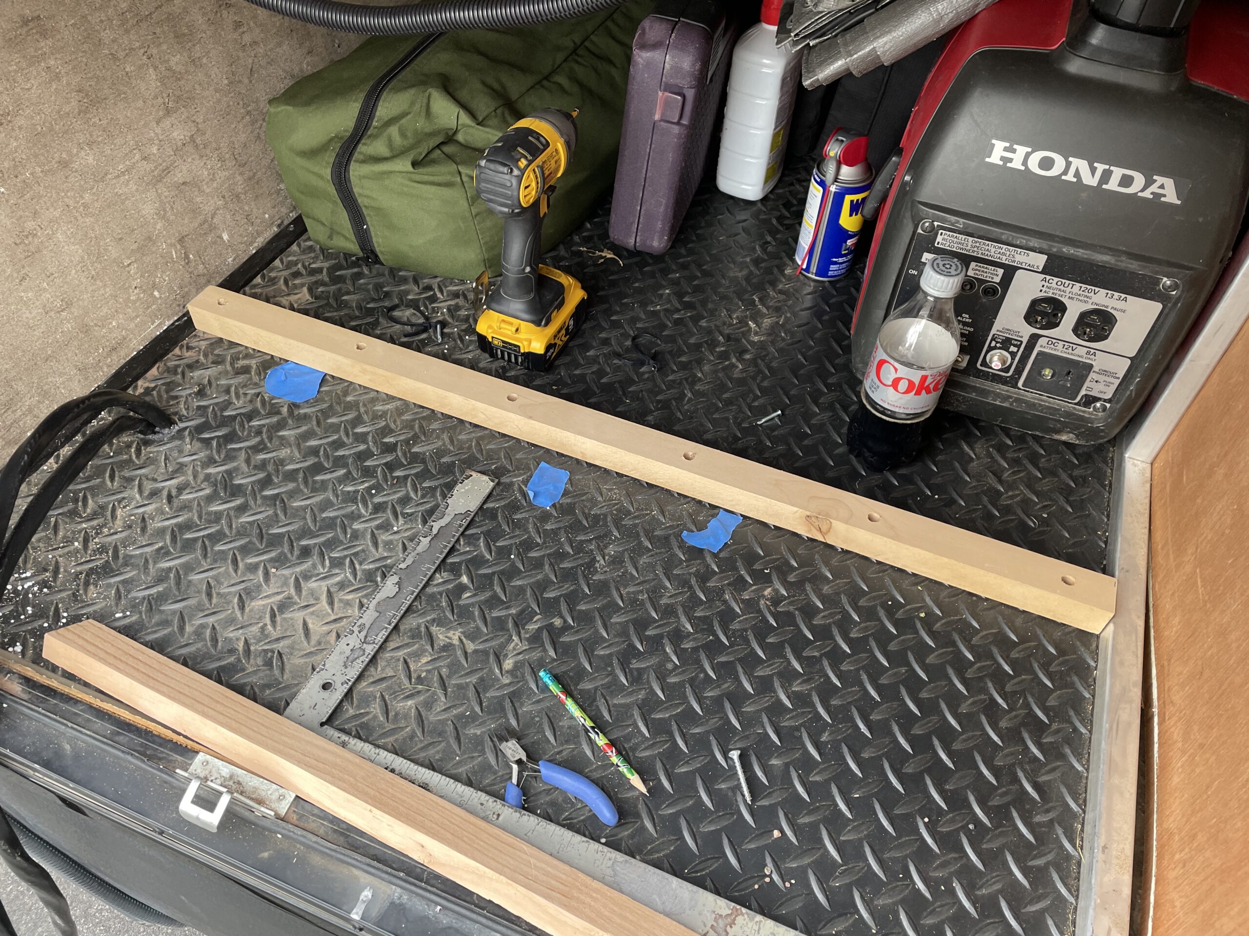
Figure 2 illustrates the physical space we’re starting with and some essential tools, Dewalt impact drill and a Diet Coke. First, we constructed a 3/4″ plywood wall that stretches from the bottom to the top of this compartment and lies flush against the short wall near the top.

This approach required a cleat, see Figure 3, attached to the floor to support the plywood wall. To determine the location of the cleat, we held a small piece of plywood against the upper wall and marked the bottom of the compartment with blue tape where it landed when square.
The cleat, made of 1-1/4″ by 1-1/4″ lumber, was built by drilling screw holes and countersinking them to allow some 1-1/4″ screws to reach well within the 5/8″ flooring. We also had to add a top cleat, made of the same material, on the right-hand side of this space. The upper cleat was attached to the rectangular aluminum framing using 1-1/4″ self-drilling screws. Finally, before the plywood wall went up, we needed to run a few electrical wires and rescue the Diet Coke.
Initial Wiring
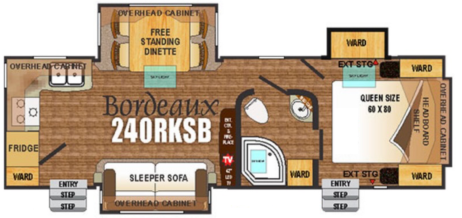
As mentioned in a previous post, our RV is a 2016 Outdoor RV Blackstone 240 RKSB. The floorplan of this model is illustrated in Figure 4. Our new power center will be located in the left-hand side of the pass-through storage area in the upper right-hand corner of Figure 4. Our shore power outlet is located at the left rear of the trailer, while our circuit breaker panel is located just under the refrigerator in the lower left of the figure.
120 Volt AC Wiring
The shore power electrical outlet is wired directly to the circuit breaker panel. However, in our design, the shore power connector must be wired to the inverter/charger, and then the inverter/charger is wired to the circuit breaker panel. We ran Southwire 6/3 Romex from the circuit breaker panel area to the power center to accommodate this need. This line will carry the 50 A shore power to the inverter/charger. We then ran a second piece of 6/3 Romex from the power center back to the circuit panel area. This wire will carry inverter/charger output to the circuit breaker panel to energize our appliances.
Many discussions in RV forums berate Romex because it shouldn’t be used in high vibration environments like RVs and boats. However, Southwire Romex larger than 10 AWG uses stranded wire for three conductors and a solid ground wire. Therefore, we used Romex instead of running a PVC conduit and pulling eight strands of 6 AWG THHN wire through it.
We intended to run this wire ourselves, but it was a task I was not looking forward to. However, our local RV center, where we purchased our trailer several years ago, was willing to run the Romex for a few hundred dollars. That was a deal we couldn’t pass up. They ran the wire neatly and securely and left extra wire coiled behind the circuit breaker panel and in our power center.
Solar PV Wiring
The original solar setup on our trailer was a single 150 W panel on the roof. The installer fed the PV cables through the roof and into an upper cabinet in the bedroom. An inexpensive PWM solar charge controller was installed in that cabinet and then wired down through the trailer cap to the a-frame-mounted batteries.
Soon after purchasing the trailer, we upgraded this setup by replacing the single 150 W panel with three 200 W panels and the PWM controller with an MPPT controller. This upgrade used the existing wiring, and the new controller remained in the bedroom closet. This work aims to improve all aspects of our solar setup and get the solar charge controller out of our cupboard.
We ran new 10 AWG PV cables from the roof through the portal and into the trailer attic near the front of the trailer. Next, we routed the PV cables behind the trailer cap and into our power center. Unfortunately, we purchased 20′ lines with MC4 connectors on each end. We intended to cut the connectors off of one end and fish the cable to its destination. However, we inadvertently cut off the wrong connectors and ended up having to install our own. We should have purchased cable and installed MC4 connectors after they were in place.
Battery and House Wiring
Eventually, as described in our previous post, we will move our battery bank and will need to provide 12 V from our power center to the rest of our trailer. For now, the batteries remain on the a-frame and feed the rest of the trailer from there. Therefore, we need to tap into the existing 12 V and ground line so our new solar charge controller can charge the batteries. Our completed project will eliminate the lines to the batteries.
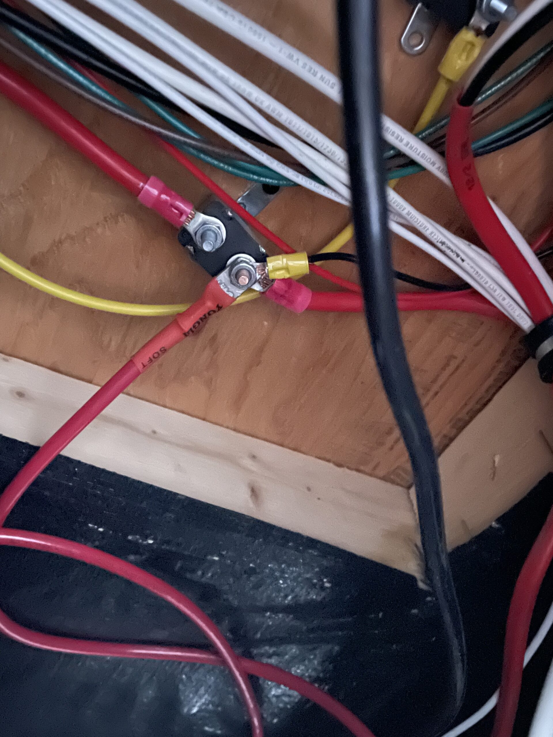
On the underside of the subfloor near the a-frame of our trailer, we found several auto reset circuit breakers. The breaker illustrated in Figure 6 has a direct connection to the positive terminal of our batteries. The positive terminal of our batteries and the trailer emergency brake are attached to the shown stud. We attached a 6 AWG THHN wire with a lug to that terminal and fished the wire into our power center.
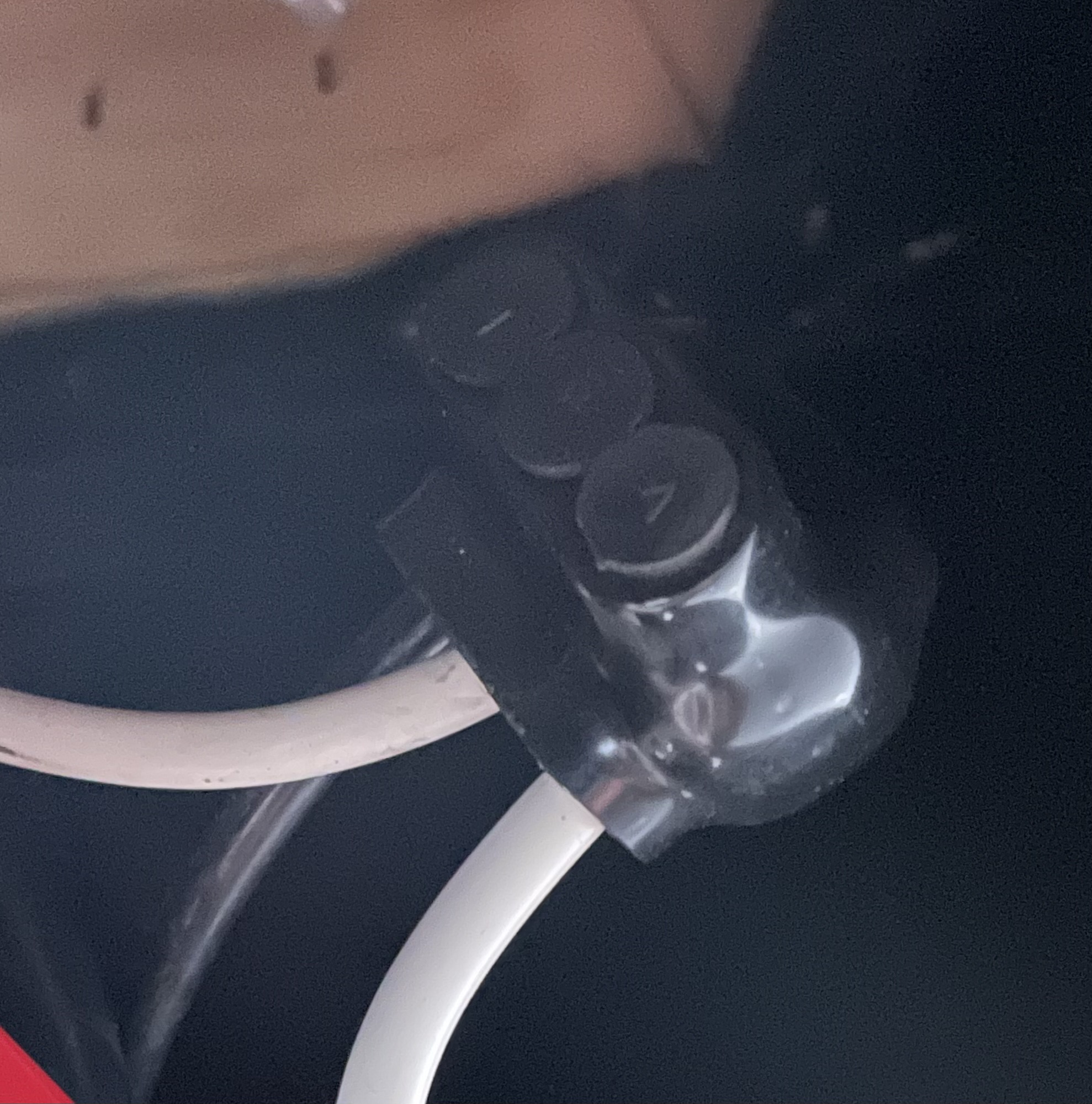
A ground wire also travels through this area from the negative terminal of our batteries and into the trailer. We obtained ground by cutting the ground wire that travels through this space and connected both ends and a new 6 AWG THHN wire with a 3 position Morris connector, illustrated in Figure 7. These connectors are amazing and easy to use. Finally, we fished the new ground wire into our power center.
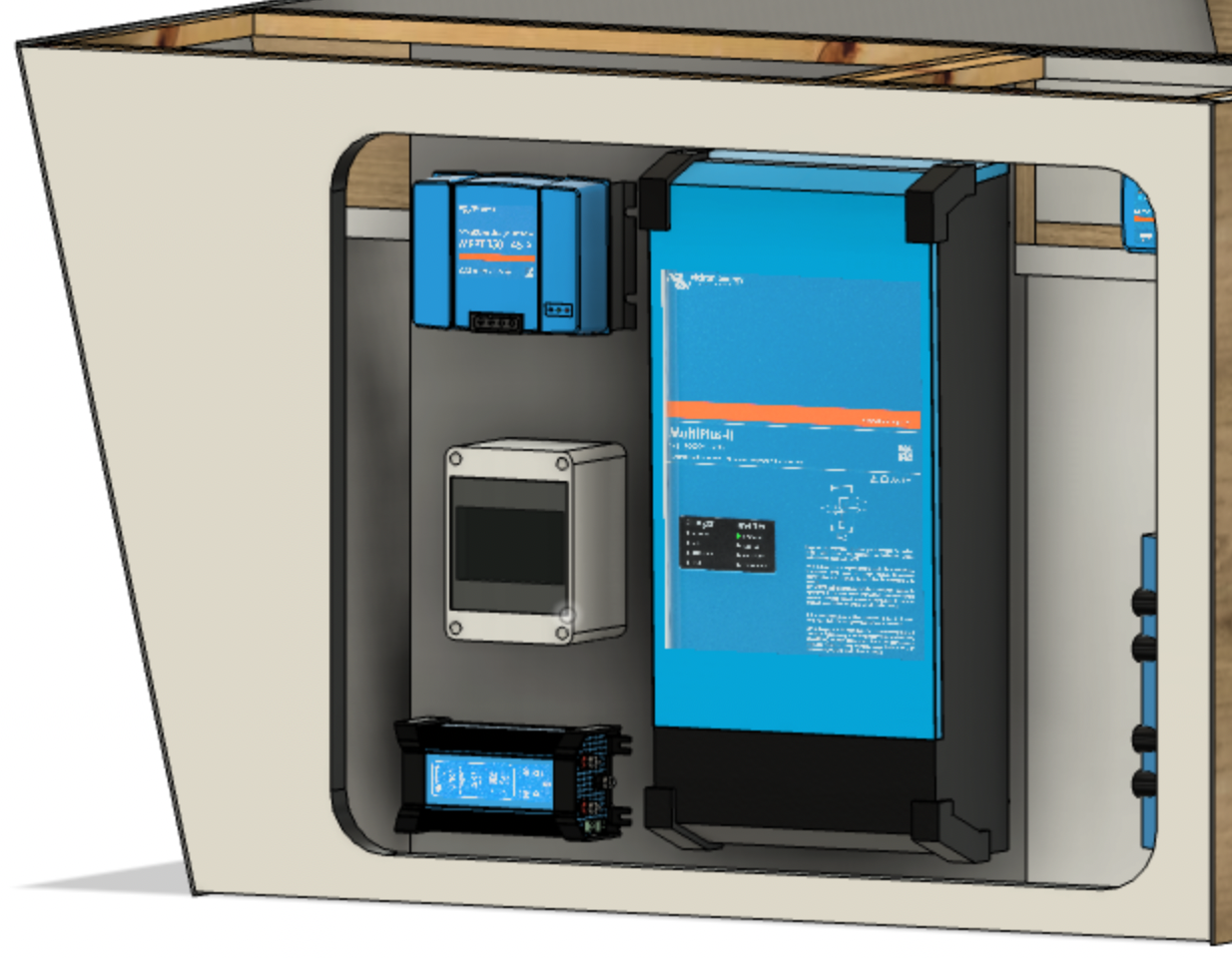
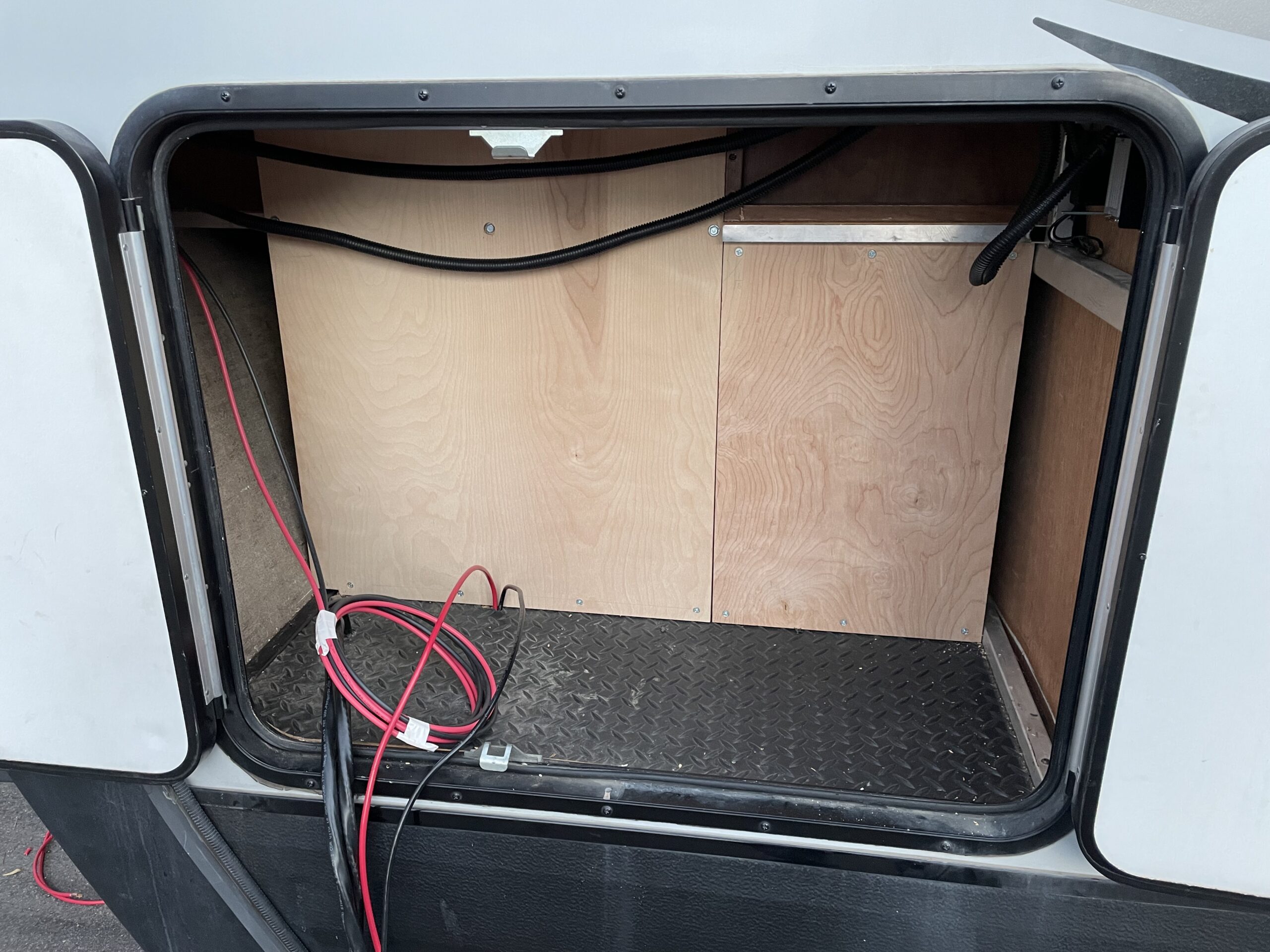
After the 120 V AC, solar PV, and 12 V DC wiring were complete, we installed the plywood walls. With this done, the power center is ready for the addition of components. The empty power center can be seen in Figure 8.
Solar Additions
On the roof of our trailer, we installed a fourth 200 W solar panel, as illustrated in Figure 9. We couldn’t obtain another panel identical to the three we had, so we chose a panel with similar voltage characteristics and a current capability that slightly surpassed our existing panels. This panel will not constrain our system or be significantly limited by our existing panels; it should be a good match.

Before celebrating the installation of our new panel or our wire routing prowess, we measured a voltage of 60 V across the PV cables. The addition of the fourth panel increased the PV voltage to approximately 80 V; success!
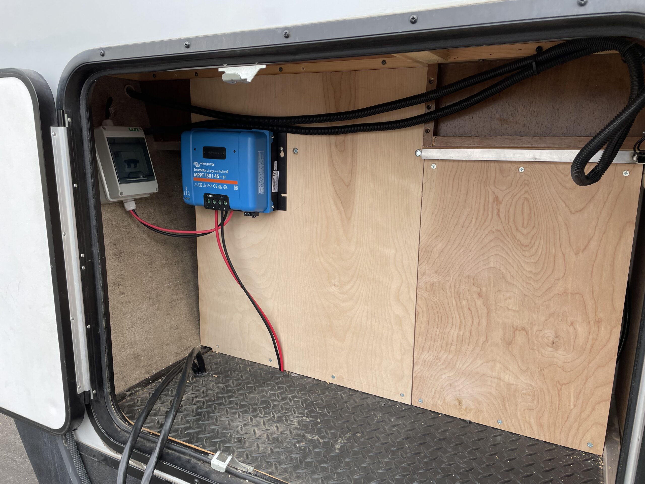
We connected the PV cables to a disconnect switch/circuit breaker mounted in a DIN breaker box in our power center. Next, we used a couple of short lengths of PV cable to run from the breaker box to our Victron SmartSolar 150-45 solar charge controller. Finally, we connected our 12 V DC lines to the solar charger, and we’re back in business. Figure 10 illustrates the result.
The End Result
We’ve reached the end of another sub-project, and the trailer is once again ready to be used. We successfully created our power center space prepared to receive additional components. In addition, we routed all necessary power cables to this new space. Finally, we added a solar panel and upgraded our MPPT solar charge controller.