
Introduction
In my previous post, I described myDoorbell’s power supply module. In this post I will describe the circuitry that translates a standard doorbell button press into something that can be easily consumed by a microcontroller.
Standard Operation
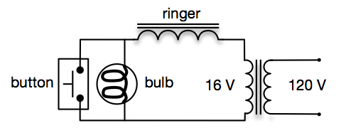
The standard doorbell circuit is shown in the following figure. Recall that when the doorbell button is not pressed (open), current flows from the transformer, through the lamp, and through the solenoid, completing the circuit. With the doorbell button open, my test setup has approximately 50 mA of current. When the button is pressed (closed) a larger current, approximately 1 A, flows through the circuit.
myDoorbell is complicated by the system requirement to use the existing doorbell button and retain the functionality of its lamp.
myDoorbell Button
The figure above can be represented by a schematic where the lamp is replaced by a 320 Ω resistor. We model the lamp with this value resistor because with 16 Vrms across it, the current flow is ~50 mA.
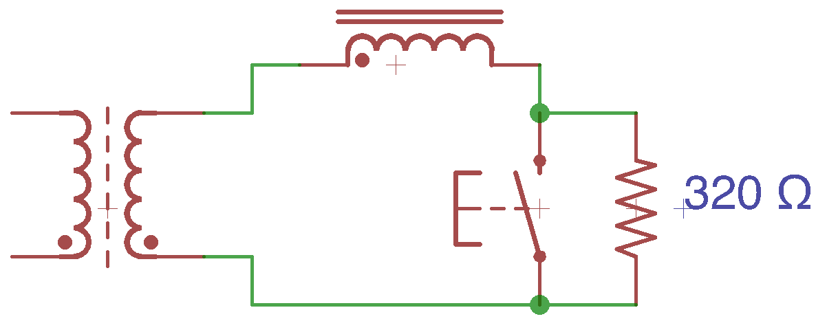
myDoorbell does not need the solenoid in the above circuit. However, if we simply replace it with a wire we will create a short circuit when the button is closed. In this case, approximately 0 Ω will exist, resulting in nearly infinite current, a bad idea. So replacing the solenoid with a resistor, to limit current, is necessary, but what value still needs to be determined. A large value resistor will result in little current, which is attractive, but too little current and the lamp won’t be bright enough to be useful.
As previously discussed, resistors have resistance values measured in Ω’s, but they are also rated for the amount of power they can dissipate. The power dissipated by a resistor is equal to the product of the voltage across it and the current through it. Through manipulation of Ohms Law it can be shown that the power dissipated by a resistor is also equal to the product of its value and the square of the current through it. With this in mind, if we choose a low value resistor its power rating will need to be increased.
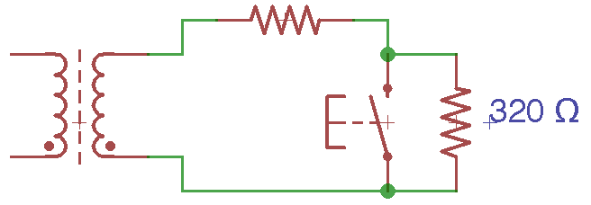
For example, if we choose a 10 Ω resistor, for the top resistor in the above figure, then approximately 48 mA will flow through the lamp when the button is open. The 10 Ω resistor will have to dissipate 0.02 W, well below the 0.1 W rating typical for small surface mount resistors. However, when the button is closed 1.6 A will flow through the circuit and the resistor must dissipate 25.6 W, it’s going to catch fire!
Let’s choose a higher value resistor, say 10 kΩ. Now when the button is open approximately 1.6 mA of current flows through the circuit resulting in the 10 kΩ resistor dissipating just 0.02 W, which is great, but the lamp will be very dark, bad!
So let’s compromise. We’ll choose a 220 Ω resistor that results in a current flow of 29 mA and a lamp that is visible when the button is open. In this mode the 220 Ω resistor will dissipate 0.185 W. This will require a larger resistor, but manageable. When the button is closed the 220 Ω resistor results in a current of nearly 73 mA and a power dissipation of 1.17 W. This will require quite a large surface mount resistor, but is necessary to meet our design requirements.
Detecting the Press
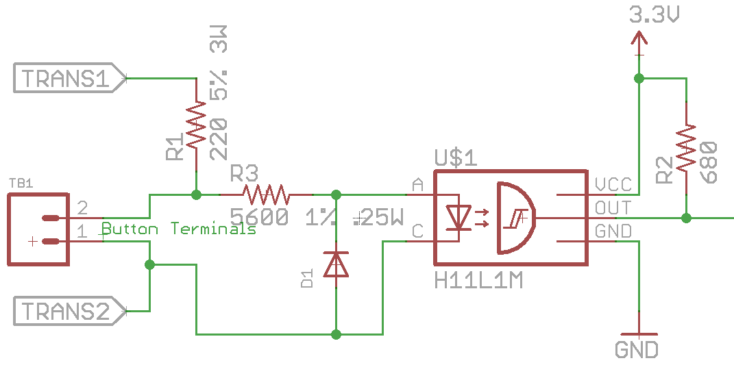
When the button is open, the voltage across it is equal to 320 Ω * Ilamp. Where Ilamp is equal to 16 Vrms / 540 Ω, or 29 mA. So the voltage across the button when it is open is 9.48 Vrms. When the button is closed, the voltage across it is 0 V. What we need is a circuit that detects this difference and generates a DC voltage appropriate for an input to a 3.3 V microcontroller. The figure below depicts just such a circuit.
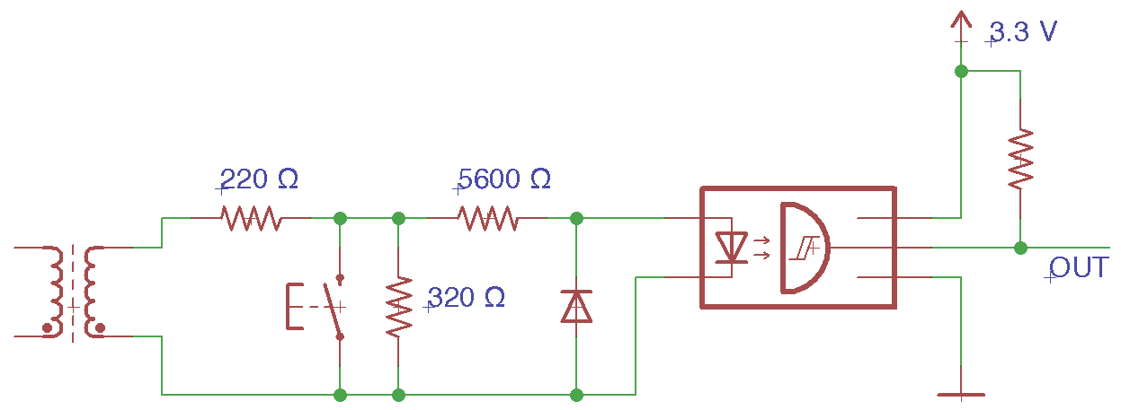
To the left we see the portion of the circuit described earlier, consisting of the transformer, push button, the 320 Ω resistor representing the lamp, and the 220 Ω resistor added to restrict the current flow when the button is closed. The circuitry to the right needs explaining.
Let’s start with the component outlined in the rectangle, an optocoupler. This device consists of a LED that emits infrared light onto a light sensitive driver. When the input current is sufficiently high, infrared light is emitted by the LED, and the output of the driver is pulled to ground. When the input current is sufficiently low, the output is left in an “open collector” state where no current flows. With no current through the output resistor, there is no voltage drop across it. In this state, the output level is equal to the voltage attached to the other side of the output resistor, in our case 3.3 V. A representative device is the H11L1M. Its datasheet can be found here.
In our application, when the doorbell button is closed there is 0 V across the LED of the optocoupler and the output will be 3.3 V. When the button is open the 320 Ω resistor, representing the lamp, will have 9.48 Vrms across it. The peak voltages are -13.4 V and 13.4 V. According to the optocoupler’s datasheet, its LED cannot tolerate reverse voltages exceeding 6 V, so the external diode is added to protect it. The external diode conducts when the input voltage is negative, resulting in roughly 1 V across the LED.
Again referring to the datasheet, we need 1.6 mA of forward current on the LED to get the device to activate, driving the output low. As the input voltage rises from 0 V to 9 V we’ll allow the output to remain high, but when it arrives at 9 V we’ll switch the output to low. This will result in a 60 Hz sequence of 3.3 V pulses while the button is open. To accomplish this we need the optocoupler input current to be less than 1.6 mA with input voltages less than 9 V, and greater than 1.6 mA when the input voltage are higher.
Imagine we don’t know the value of the 5600 Ω resistor in the above circuit. To meet the requirements described in the previous paragraph, we need to size this resistor appropriately. If there is 9 V on the left of the resistor and 1 V on the right side, due to the forward voltage drop VF across the LED, there is 8 V across the resistor. This is explained by Kirchhoff’s Voltage Law that states that the sum of voltages around a loop must be zero. To get 1.6 mA at 8 V we need a 5 kΩ resistor, we’ll use the more common 5600 Ω device. At our peak voltage of 13.4 V, we’ll have 2.2 mA of current through the optocoupler’s LED, well below the 30 mA maximum value the device can handle.
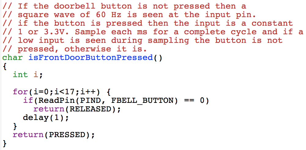
If the optocoupler’s output signal is tied to the input line of a microcontroller, a simple software missing pulse detector can be used to detect when the doorbell button is closed, see the sample below. In this example we check the value of the optocoupler’s output once each ms for one 60 Hz cycle, or one 17 ms period. If it is ever zero the button is open.
Physical Implementation
Our design is sensitive to the value of R3, the 5600 Ω resistor. For this reason we chose a device with a 1% tolerance. This costs a bit more, but in this case it was important. Also note that we chose a 3W resistor for R1 to ensure we don’t have a catastrophic failure, a fire!
The printed circuit board layout for the above design is shown below. The pads on the far left are for TB1 which is a connector where the two wires from the doorbell button are connected. Notice R2 in the lower right hand corner of the PCB. It is the 680 Ω output resistor and is a normal sized surface mount resistor. Compare this to the size of R1 which is the 220 Ω 3 W resistor, quite large in comparison.
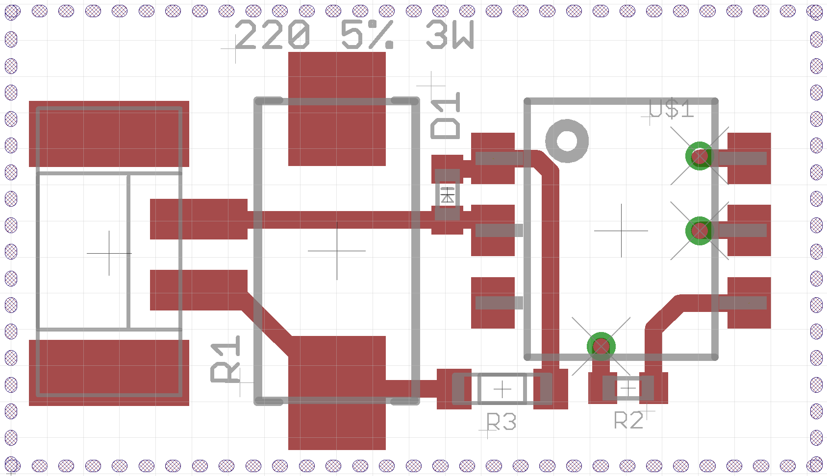
This circuit results in a simple layout that doesn’t require a 4-layer PCB. However, to simplify connections to other myDoorbell modules, a 4-layer technology was used. No routing on the bottom of the board was required. The inner layers are used for ground and 3.3 V and are brought to the top layer using the three visible vias.

When integrated into the final system, small changes were made to optimize the overall layout. In the above photo of the myDoorbell button detection module, you’ll notice that the two smaller resistors and the diode have been move to slightly different locations. The final system contains two of these modules, one for the front door and the other for the rear door.
Outcomes and Artifacts
This post describes a simple circuit and associated software that meets the requirements of keeping the doorbell lamp functional and detecting when the button is pressed. There are likely many alternative techniques for meeting these requirements, but one worth considering is to use an AC line monitor chip such as the MID400 which is intended to raise a signal if the power line voltage is interrupted. In our scenario it would raise a signal if the AC voltage across the doorbell button was absent, or in other words, the button is pressed. This unit costs slightly more than the circuit described above, but would eliminate the need for the external diode and the missing pulse detector software. The output could be tied to a microcontroller interrupt line making the system more responsive, reliable, and perhaps simpler.
The Eagle schematic and PCB files are available from the myDoorbell repository at github.com.
Basics to Remember
The power dissipated by a resistor is equal to the product of the voltage across it and the current through it, P = VI. However, we often don’t know the voltage across a resistor, but rather know the resistance value and the current through it. In this case a simple manipulation of Ohm’s Law yields a solution, P = I2R.
The sum of voltages around a circuit loop must be zero. This fact is known as Kirchhoff’s Voltage Law. It is useful for circuit analysis and as used in this post to determine the proper circuit element values to meet requirements.