Introduction
In my previous post, I described the nine modules that make up myDoorbell. While we could begin our discussion with any one of the nine modules, the one all others are dependent on is the power supply. What the power supply is intended to do is convert the source characteristics we have, to the supply characteristics we need. In other words, it needs to convert the 16 volt (V) alternating current (AC) available in the doorbell-wiring box to a direct current (DC) voltage appropriate for our use.
What myDoorbell Needs
Reviewing the datasheets of components, likely to fulfill the function of each of the other eight modules, led me to believe that seven of the eight modules need a 3.3 volt (V) supply. The Audio Amplifier module is the exception.
Audio amplifiers are designed to take small signal inputs and accurately reproduce them with additional power. Like the other modules, the amplifier is powered by a DC source. Since power is equal to the product of voltage and current, it is possible to increase the power of the output signal by increasing its voltage, current or both. It is impractical to use the 3.3 V DC source for the audio amplifier given that we have an upper bound on the available current of just over 1 ampere (A). This combination would result in a 3.3 watt (W) (3.3 V * 1 A) maximum output power. This is insufficient power to drive a speaker at the volume necessary for a doorbell. The better option is to convert the 16 V AC source to the highest voltage DC source conveniently available.
So myDoorbell needs are simple, a 3.3 V DC supply for the digital components and the highest practical DC voltage available for the Audio Amplifier module.
Basic DC Power Supply
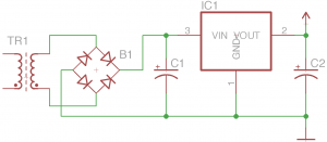
A simple DC power supply is illustrated below. The AC input is connected to the primary terminals on the left of transformer, TR1. This AC input is a sine wave that swings from a negative to a positive peak with a frequency in the U.S. of 60 cycles per second, or 60 Hz. AC voltages are typically described in terms of their root-mean-squared or rms values. Their peak and rms values are related by, Vrms = 0.707 * Vpeak. In the U.S. a common input voltage is 120 Vrms.
In a typical application, the transformers job is to reduce the input voltage to a voltage just slightly above the desired power supply output voltage. For example, if the desired output voltage is 3.3 V DC, a transformer that transforms 120 Vrms to 5 Vrms may be appropriate. A typical transformer works by having two electrically insulated coils of wire wrapped around a common ferrite core. The coil connected to the input is called the primary, while the other is called the secondary. The ratio of turns on the secondary to primary coils determines how the secondary voltage compares to the primary voltage. For the above example, the primary coil should have 120 V / 5 V = 24 times as many turns as the secondary.
The full-wave bridge rectifier, B1, inverts the negative half-cycles of the transformers output voltage and passes both half-cycles to the output of the rectifier. While this output is DC, the waveform has significant ripple, varying from zero to the positive peak at 120 Hz. The ripple is reduced by capacitor C1 which brings the voltage across C1 to nearly the peak value of the rectifiers output. IC1 is an integrated linear voltage regulator that typically takes a voltage input higher than the desired output voltage and locks its output to the target voltage. Finally, C2 reduces the remaining ripple to tolerable levels.
Continuing with our example, the output of the transformer is 5 Vrms. The full-wave bridge rectifier creates a 120 Hz DC voltage that varies from 0 V to 5 V / 0.707 or 7.07 V. Capacitor C1 reduces the ripple and presents a fairly constant 7.07 V DC input to the voltage regulator. The voltage regulator locks its output to the desired 3.3 V level and most of the remaining ripple is removed by capacitor, C2.
myDoorbell Power Supply
It took me three attempts to find a satisfactory design for the myDoorbell power supply. Recall that the goal is a DC power supply that can power seven of the eight modules at 3.3 V DC and the amplifier with the highest voltage conveniently available. The seven digital modules consume a total of approximately 300 mA or 0.3 A of current at 3.3 V. To provide a margin of safety we will design the power supply to provide 500 mA. The DC voltage at the input of the voltage regulator is equal to 16 Vrms / 0.707 or 22.6 V DC. This will be used for the Audio Amplifier module.
Attempt 1 – Linear Voltage Regulators
The most straightforward DC power supply design for myDoorbell follows the design pattern illustrated earlier. In this simple design the voltage regulator is a simple three pin linear regulator. However, through sad experience this approach doesn’t work in this application because of the large difference between the 22.6 V regulator input voltage and the desired 3.3 V DC power supply output. In our earlier example, the designer was free to pick a transformer that reduced the input supply voltage to a reasonable level. In the myDoorbell world we are stuck with the doorbell transformer that reduces the 120 Vrms line voltage to the available 16 Vrms. This results in the 22.6 V regulator input voltage and the issues using the linear regulator.
The power dissipated by the linear voltage regulator is equal to the product of the voltage across the device and the current through it.
Pregulator = Vregulator * IregulatorPregulator = (Vin – Vout) * IregulatorPregulator = (22.6 V – 3.3 V) * 0.5 APregulator = 19.3 V * 0.5 APregulator = 9.6 W
This is a significant amount of power that is presented as heat. Without a significant metal heatsink being thermally attached to the voltage regulator it will consume itself. In fact my first design did just that. I was taught that digital electronic systems work because of magic smoke contained in them. When I naively built and tested this design the device overheated, the magic smoke escaped, and the device no longer functioned. While this power supply design is not feasible for myDoorbell, it might effectively test your smoke detectors.
Attempt 2 – DC to DC Converter
After licking my wounds of defeat I came across a device that I thought would fit my needs perfectly, a DC to DC converter. This device is essentially a small power supply integrated into a single package. This device accepted a broad range of input voltages and output 3.3 V at up to 500 mA, a perfect fit.
However, the particular device I chose had a “feature” that caught my eye as a positive thing, but ended up being a show stopper. The grounds on the input and output of the chosen device were isolated. This sounds like a good thing, but after prototyping myDoorbell and debugging for a significant amount of time, a serious design flaw was discovered.
Recall that the audio amplifier will operate from the highest DC voltage conveniently available to us. Well the highest voltage available is the DC voltage just before the DC to DC converter. The voltage available at that location is 22.6 V and is ideal for our audio amplifier. However, the digital electronics will be operating on the opposite side of the DC to DC converter. This includes the MP3 to audio converter that outputs the low voltage audio signal to be amplified. Voltage is an across variable or the potential across two points, typically the signal and a reference ground. In this particular design the MP3 decoder and the audio amplifier share the signal line, but not a common reference. If these grounds are connected, the DC to DC converter does not function properly, if they are not connected, the audio subsystem does not work. Another failure!
After making another design choice, I discovered that there are DC to DC converters that are non-isolated. While this would have worked, a better design in terms of cost exists.
Attempt 3 – Switching Voltage Regulators
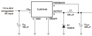
Switching voltage regulators are an alternative to the linear device discussed above. A very simplistic description of how this device operates goes something like this. The device checks the voltage across the capacitor on its output and if it is below the target voltage, the device charges the capacitor. If the voltage on the capacitor is at or slightly above the desired voltage, the device allows the capacitor to discharge. This switching occurs thousands of time per second resulting in small swings between minimum and maximum values. This regulator dissipates far less power and can easily function without a heatsink. The tradeoff is that this device requires a few more components as shown in the following figure taken from the Texas Instruments TL2575 datasheet.
According to the datasheet capacitor Cin stabilizes the regulator, Cout reduces ripple on the output, while diode, D1, and inductor (coil), L1, reduce high frequency noise. The design, shown below, comes from the datasheet with some slight modifications. According to the datasheet, the size of the inductor depends on the output voltage and current characteristics. Referring to the graph included in the datasheet, we chose a 0.001 Henry, 1 mH, inductor. My complete and successful design is illustrated below.
The light emitting diode (LED) and resistor R1 were added to yield a simple power on indicator. The transformer, TR1, is the doorbell transformer and is shown solely for clarity and is not included in the final design. The voltage available after the full-wave bridge rectifier is approximately 22.6 V of smoothed (filtered) DC, perfect for our audio amplifier. The final output is our desired 3.3 V regulated and smooth DC supply, perfect for the remaining digital components making up the system.
Physical Implementation
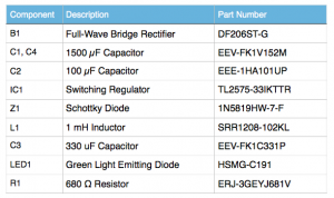
This section describes the design process used to implement the above schematic in a surface mount printed circuit board (PCB). We begin by identifying the components that are required, see below.
While I used the Eagle computer aided design (CAD) tool to input the above schematic and realize the PCB output files, any reasonable tool will do. Most PCB tools have thousands of predefined library components, but I prefer to build my own library parts because I suffer from the dreaded, not invented here syndrome.
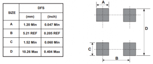
I will illustrate my process for building these library components for the full-wave bridge rectifier, but the same process would be followed for all components used. From the rectifier datasheet we can extract the “suggested pad layout”. If the datasheet for a particular device does not include this, then I select another vendor’s product, that simple! The pad layout is the copper pattern that will be left on the PCB where this device is electrically and mechanically connected using solder. The suggested pad layout for the full-wave bridge rectifier, DF206ST-G, is shown below.
This pattern is added to the library of components and associated with the components schematic drawing. This process is completed for all necessary components.
The schematic is built by placing the selected components and wiring them as illustrated. In Eagle you then convert this to a PCB that results in each component being placed on the PCB with lines connecting the appropriate signal pins. The components are moved into appropriate positions by the designer and the lines are replaced with copper interconnects either automatically or by hand.
Printed circuit boards are made up of layers of conductive material, such as copper, separated by layers of insulation. Layers can be connected through a via. The top and bottom layers are typically covered with a material that doesn’t easily adhere to solder. These layers have openings where solder and components are to be connected to the copper traces.
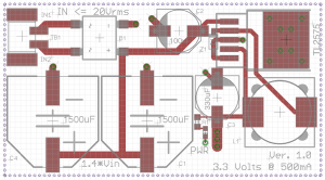
For myDoorbell I decided to use a 4-layer PCB process. This process has a layer of copper on the top and another on the bottom and two internal layers. The top and bottom layers are used to route interconnections. One of the internal layers is used to distribute 3.3 V to the entire system. The second internal layer is tied to ground and distributed throughout the design. These internal layers are often called planes. While myDoorbell is reasonably simple and might have been possible with a two layer design, having a ground and power plane results in a safe and simplified design. The top view of the resulting power supply PCB is shown below.
Those items represented in gray indicate labels and component outlines that will be visible on the completed board. The red areas represent the copper pads and interconnects on the top layer of the board. This board does not have any copper on the bottom layer. The green circles indicate where a via is used to connect the top copper to either the ground or 3.3 V planes. The dotted lines around the board represent the 3.3 V and ground planes.
In the upper left hand corner of the board there is a component we have not yet discussed. It is a simple connector where the two wires from the doorbell transformer are connected to the power supply. These feed directly into the full-wave bridge rectifier to the right. The positive output terminal of the rectifier is connected to the positive terminals of the capacitors, C1, C2, and C4, as well as the input of the regulator. The negative side of the rectifier is connected to ground through the via to its upper right. All other devices connected to ground do so through a via to the ground plane.
Due to the laws of physics, each wire is also an inductor and as such resit changes in current flow. The longer the wire, the more inductance it will have. For this reason it is good practice to minimize the length of wires connecting components, especially those that are high speed such as the switching regulator. You’ll notice that C1, C3, and Z1 are close to the regulator. One reason internal ground and power planes are useful is because they facilitate the close connection of components, reducing wire length, and inductance.
The large copper area in the upper right corner of the board connected to the ground plane through 8 via connections is where the regulator is physically connected to the board. The heat from the regulator flows through its body, onto this copper pad, and into the ground plane. This acts as a heatsink pulling the heat away from the device.
Note that the positive terminal of C3 connects to the 3.3 V internal plane through three via connections. Later this same 3.3 V plane will be connected to the rest of the myDoorbell circuit. The positive side of the rectifier component is the source of the 22.6 V that will be used by the audio amplifier.
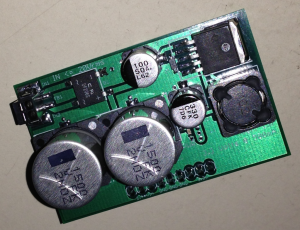
The resulting PCB measures 59mm in length and is 32mm wide. For testing purposes it was increased in size to allow for the inclusion of a set of header pins for easy insertion into a prototyping board. This breakout board is illustrated below. The tested board delivered 3.3 V at 400 mA and 22.6 V at nearly 1 A. This perfectly matches the needs of myDoorbell. Success at last!
Outcomes and Artifacts
Outcomes include lots of learning, a useful DC power supply design, and a working version implemented as a 4-layer PCB with surface mount components. The circuit is capable of inputs up to 20 Vrms resulting in a high voltage output of just over 28 V DC. By simply replacing the regulator with a product family substitute, the low voltage output can be changed to 5 V, 12 V, or 15 V. The schematic, PCB layout, and bill of materials can be acquired from github.
Basics to Remember
The relationship between peak and rms voltages is described by, Vrms = 0.707 * Vpeak.
Ohms Law states that voltage (V) is equal to the product of current (I) and resistance (R). voltage is measured in volts (V), current is measured in amperes (A) and resistance is measured in ohms (Ω).
Resistors (R) are measured in ohms (Ω), capacitors (C) are measured in farads (F), and inductors (L) are measured in henrys (H).
Due to the laws of physics, each wire is also an inductor and as such resit changes in current flow. The longer the wire, the more inductance it will have. For this reason it is good practice to minimize the length of wires connecting components, especially those that are high speed.
Component datasheets are our friends and we should get use to reading them, understanding them, and referring back to them often. They look long and complex, but you’ll get use to them.
Datasheets often have a “Typical Application” section that illustrates how the component can be used. This schematic can often be used as is or with minor modifications for your application.
LEDs can only handle so much current before their magic smoke escapes. The more current that flows through them, the brighter they are, within limits. 5 – 10 mA of current seems about right for many applications. The resistor in series with a LED is intended to limit the current. If you assume the voltage drop across a LED is 0 V, then the entire potential is across the resistor. Ohms Law states that the voltage is equal to the product of current and resistance, so the resistance is equal to the voltage divided by the current. In our example power supply, the voltage across the resistor is 3.3 V, so to limit the current to 5 mA we need a resistor of 3.3 V / 0.005 A = 660 Ω. Since resistors come in standard values we’ll use the closest standard value of 680 Ω.

