Introduction
Telescopes that slew to, and track celestial objects do so through the use of electric motors that drive their axes of rotation. Portable telescopes, like the Celestron CPC 1100 GPS, depend on either alternating current (AC) line voltage or batteries for their power. In addition, camera coolers, dew heaters and other accessories require power. The remainder of this post describes power requirements of typical astrophotography equipment and the construction of a do-it-yourself (DIY) portable power supply.
Astrophotography Equipment
The equipment I use includes a telescope, camera and dew heaters:
- Celestron CPC 1100 GPS XLT Telescope
- ZWO ASI071MC Pro
- Dew Not 11″ Dew Heater Strip DN012
- Dew Not 2″ Eyepiece Dew Heater Strip DN003
- Thousand Oaks Four-Channel Digital Dew Heater Control Unit
This equipment and their power requirements are listed in the following table.
| Equipment | Make and Model | Operating Voltage | Reported Current |
|---|---|---|---|
| Telescope | Celestron CPC 1100 GPS | 12 V | 1.5 A |
| Camera | ZWO ASI071MC Pro | 12 V | 3 A |
| Dew Heater | Dew-Not DN012 | 12 V | 1.57 A |
| Dew Heater | Dew-Not DN003 | 12 V | 350 mA |
| Dew Heater Controller | Thousand Oaks Four-Channel | 12 V | Negligible |
| Total | 6.42 A |
The reported values were obtained from vendor web sites, while the measured values were observed during operation. The total required current has a maximum value of 6.42 Amperes. The remainder of this post will describe the construction of a DIY power supply to meet these needs.
Power Supply
This section describes the construction of a portable power supply that meets the needs of my astrophotography equipment. This system must be portable and supply 12 Volts at just over 6 Amperes for 4-5 hours. We’ll first list the items needed and then dive into the simple construction.
Tools and Parts
This project is very straightforward and requires very few tools and a handful, a heavy handful, of parts. You’ll need a 1.25 inch hole saw or drill bit, a couple of wrenches, and scissors or a utility knife. In addition to these tools you’ll need the following items or appropriate substitutes:
- Wise Outdoors 5604-13 Large Utility Dry Box, Green
- Tinksky Waterproof 12V Cigarette Lighter Power Socket
- Werker WKDS12-33JUS or an equivalent battery. According to the battery manufacturer, this battery will supply 5.6 Amperes for 5 hours; this should meet our needs.
- Appropriate bolts, washers and nuts
Construction
Lets start with the green utility box pictured to the right. Remove the inside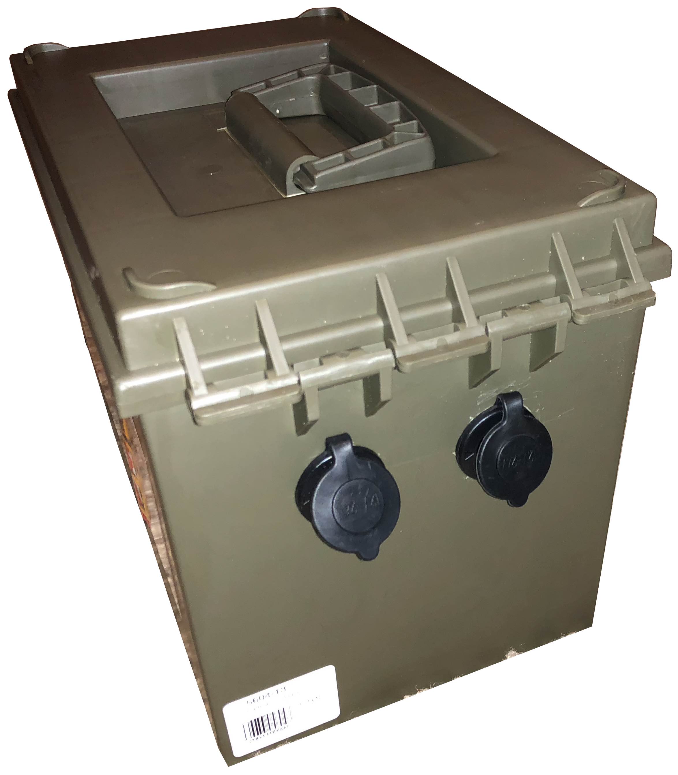 dividers and then drill two holes in one of the ends. These 1.25″ holes will enable the mounting of the 12 Volt receptacles and can be placed wherever you’d like them. Then install and securely tighten the receptacles in place.
The next step is to make a secure location for the battery to sit in the box. Place a 1/2″ layer of closed cell foam in the bottom of the utility box. Then add two 1″ thick 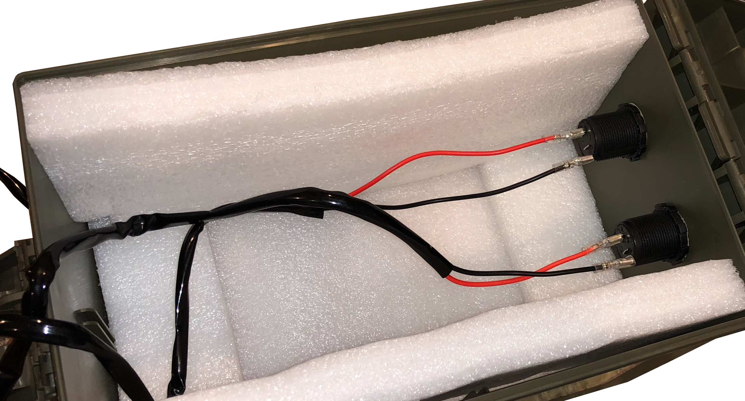 blocks of foam to each end with just enough space between them to squeeze in the battery. Then add 1″ thick foam on both sides of the box to hold the battery firmly in place. In the image to the left you can easily see the indentation in the bottom of the box intended to accept the battery.
The cigarette lighter power sockets include simple wiring harnesses that enable them to be easily connected to a battery. Connect each harness to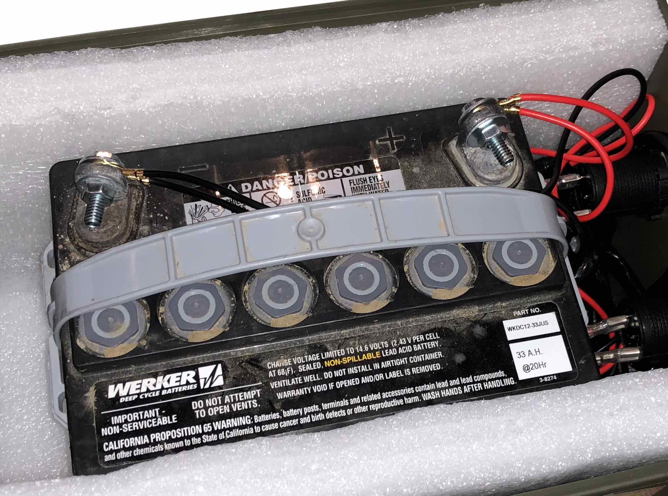 the battery with two 1″ x 1/4″ bolts with associated nuts and washers. The socket end of the harness simply plugs into the blades protruding from the power sockets. Make sure you tie the positive socket terminal to the positive side of the battery! Once this is done you simply tuck the wires neatly under the power sockets, slip the battery in place and latch the lid closed.
You now have a portable source of 12 Volt power. When the battery needs recharging, you simply open the lid and charge it.
Summary
In this post we outlined the need for 12 Volt power for remote astrophotography and presented a simple DIY power supply to meet the need.
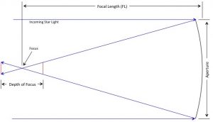
 , formed by the sides of the cone at the focus, is
![\[ \theta_{cone} = 2 \sin^{-1}(\frac{\text{Aperture}}{2 \times \text{Focal Length}}) \]](https://kelly.flanagan.io/wp-content/ql-cache/quicklatex.com-85d735a47c5f110e194d149af7651594_l3.png "Rendered by QuickLaTeX.com")
![\[ \theta_{cone} = 2 \sin^{-1}(\frac{1}{2 \times \text{f-number}}) \]](https://kelly.flanagan.io/wp-content/ql-cache/quicklatex.com-13fd8754f1ea9cf8df047752e06e5edd_l3.png "Rendered by QuickLaTeX.com")
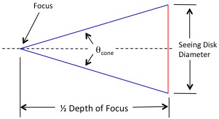
![\[ \frac{1}{2}F_{depth} = \frac{\frac{1}{2}D_{size}}{\tan \frac{\theta_{cone}}{2}} \]](https://kelly.flanagan.io/wp-content/ql-cache/quicklatex.com-2d2b84fb2adf3cbbd7f7ab57f7622bcf_l3.png "Rendered by QuickLaTeX.com")
![\[ F_{depth} = \frac{D_{size}}{\tan \frac{\theta_{cone}}{2}} \]](https://kelly.flanagan.io/wp-content/ql-cache/quicklatex.com-549cddc5792752303d492b1060d12daf_l3.png "Rendered by QuickLaTeX.com")
 is the depth of focus in meters,
  is the size of the seeing disk in meters and
 ![\[ D_{size} = \frac{2\pi}{360} \theta_{disk} \times \text{Focal Length} \]](https://kelly.flanagan.io/wp-content/ql-cache/quicklatex.com-c302c8c71436791e9a6a170001895e9b_l3.png "Rendered by QuickLaTeX.com")
 is the angular size of the seeing disk in degrees, and Focal Length is measured in meters.
![\[ F_{depth} = \frac{\frac{2\pi}{360} \theta_{disk} \times \text{Focal Length}}{\tan (\sin^{-1}(\frac{1}{2 \times \text{f-number}}))} \]](https://kelly.flanagan.io/wp-content/ql-cache/quicklatex.com-8cf1ec36769c7d1995a547eaa3cd729d_l3.png "Rendered by QuickLaTeX.com")
![\[ F_{depth} = \frac{\frac{2\pi}{360} \theta_{disk} \times \text{Focal Length}}{\frac{(\frac{1}{2 \times \text{f-number}})}{\sqrt{1-(\frac{1}{2 \times \text{f-number}})^2}}} \]](https://kelly.flanagan.io/wp-content/ql-cache/quicklatex.com-66b4759faa00c2a1c621ddf7c3157231_l3.png "Rendered by QuickLaTeX.com")
 the above equation can be simplified.
![\[ F_{depth} = \frac{\frac{2\pi}{360} \theta_{disk} \times \text{Focal Length}}{\frac{1}{2 \times \text{f-number}}} \]](https://kelly.flanagan.io/wp-content/ql-cache/quicklatex.com-db6e2a02a6536969f0b1f49311b60b9c_l3.png "Rendered by QuickLaTeX.com")
![\[ F_{depth} = \frac{4\pi}{360} \frac{\theta_{disk}}{3600} \times \frac{(\text{Focal Length})^2}{\text{Aperture}} \]](https://kelly.flanagan.io/wp-content/ql-cache/quicklatex.com-496667bdecdb69699cddca98d329544c_l3.png "Rendered by QuickLaTeX.com")
![\[ \theta = 1.22\times\frac{\lambda}{d} \]](https://kelly.flanagan.io/wp-content/ql-cache/quicklatex.com-7cea4e6b8b980f492a18c35cde617c0b_l3.png "Rendered by QuickLaTeX.com")


![\[ \theta = \frac{360}{2\pi} \times 3600 \times 2.44\times\frac{\lambda}{d} \]](https://kelly.flanagan.io/wp-content/ql-cache/quicklatex.com-0ec98cb1c544e75f2d57e571ffaad049_l3.png "Rendered by QuickLaTeX.com")
![\[ F_{depth} = \frac{4\pi}{360} \frac{\frac{360}{2\pi} \times 3600 \times 2.44\times\frac{\lambda}{d}}{3600} \times \frac{(\text{Focal Length})^2}{\text{Aperture}} \]](https://kelly.flanagan.io/wp-content/ql-cache/quicklatex.com-71e7aedd226e9361ff2943c840814fbb_l3.png "Rendered by QuickLaTeX.com")
![\[ F_{depth} = 2 \times 2.44\times\frac{\lambda}{d} \times \frac{(\text{Focal Length})^2}{\text{Aperture}} \]](https://kelly.flanagan.io/wp-content/ql-cache/quicklatex.com-d7ad27994d194babb7e13469fd65e3a3_l3.png "Rendered by QuickLaTeX.com")
![\[ F_{depth} = 4.88 \times \lambda \times \text{f-number}^2 \]](https://kelly.flanagan.io/wp-content/ql-cache/quicklatex.com-ae70cf5a51b2b2f7572aedfb3fcea197_l3.png "Rendered by QuickLaTeX.com")