
This is the third post of an ongoing series of articles documenting and describing our significant RV electrical upgrade. In our previous post, we discussed a potential need for an alternative design and presented its schematic. We also discussed a 3D model of our finished product, and we shared our results. In this post, we describe our battery bank design, discuss where we intend to place it, and the details of making space for it.
Battery Bank Design
Our first article of this series discussed our requirement for a 400 Ah battery bank to meet our electrical needs. However, our 400 Ah requirement assumed a 12 V system. We have since determined that we’d like to implement a 24 V system that reduces our Ah requirement. To enhance clarity, we should discuss our needs in terms of Watt-hours (Wh). A 12 V system capable of delivering 400 Ah is a 4,800 Wh system. A 4,800 Wh 24 V system delivers 200 Ah. We need a battery bank design for both a 12 V and a 24 V system until we determine whether or not Victron will produce a 24 V version of their MultiPlus-II 2x 120V inverter/charger.
Whether we implement a 24 V or 12 V system, we intend to use four Lion Energy UT 1200 lithium-ion batteries to implement our battery bank. We would use their newer UT 1300 batteries, but we already own two of the UT 1200s and found two used UT 1200s for less than half the price of new units. The UT 1200s are rated at 1,152 Wh, while the UT 1300s are rated at 1,344 Wh. So while our goal was 4,800 Wh, we’ll settle for the 4,608 delivered by our four UT 1200s.
24 Volt Battery Bank
We will connect two UT 1200 batteries in series to create a 24 V set. This set can deliver 2,304 Wh, which is well below our goal. Two of these sets can be connected in parallel to yield our desired 24 V battery bank, providing 4,608 Wh. Figure 1 illustrates this configuration. This implementation also adds redundancy in case a battery fails while in the field.
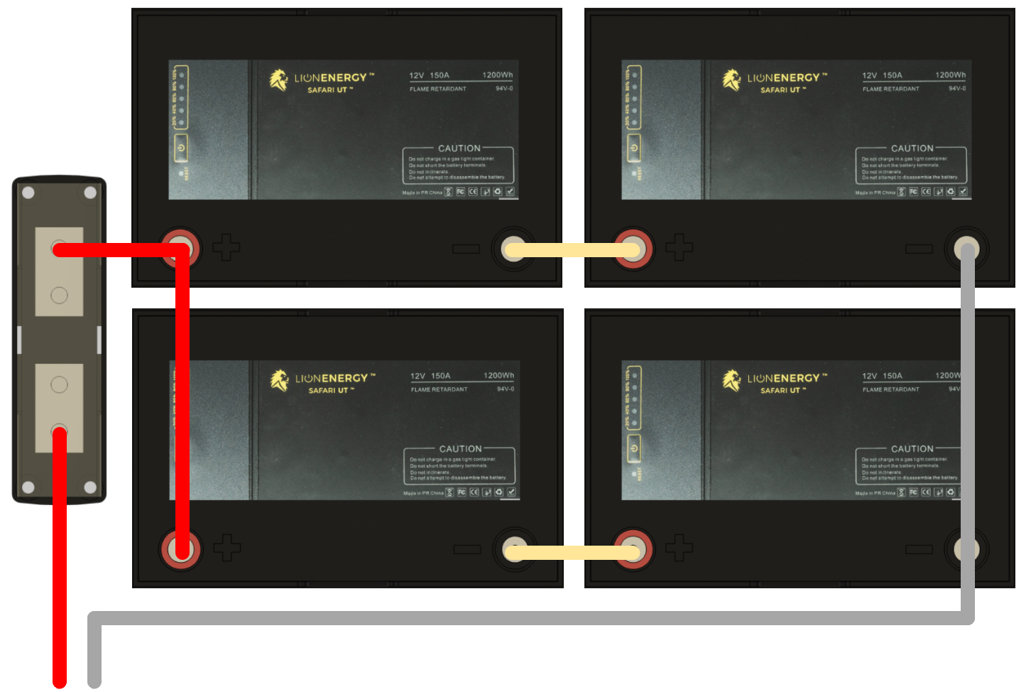
Because wire resistance is nonnegligible in these types of systems, it is essential that the circuit length from the positive terminal of any battery, through the load, and back to the negative terminal of the same battery be equal for all batteries in the bank. In practice, this means that the connecting wires between batteries should be of equal length, and the positive and negative connections to the load should be from opposite ends of the battery bank. For example, Figure 1 shows that the positive connection comes from the upper bank, while the negative connection comes from the lower bank.
According to a comprehensive document published by Victron Energy called Wiring Unlimited, an alternative configuration includes a connection between the midpoints of both sets. This configuration is illustrated in Figure 2.
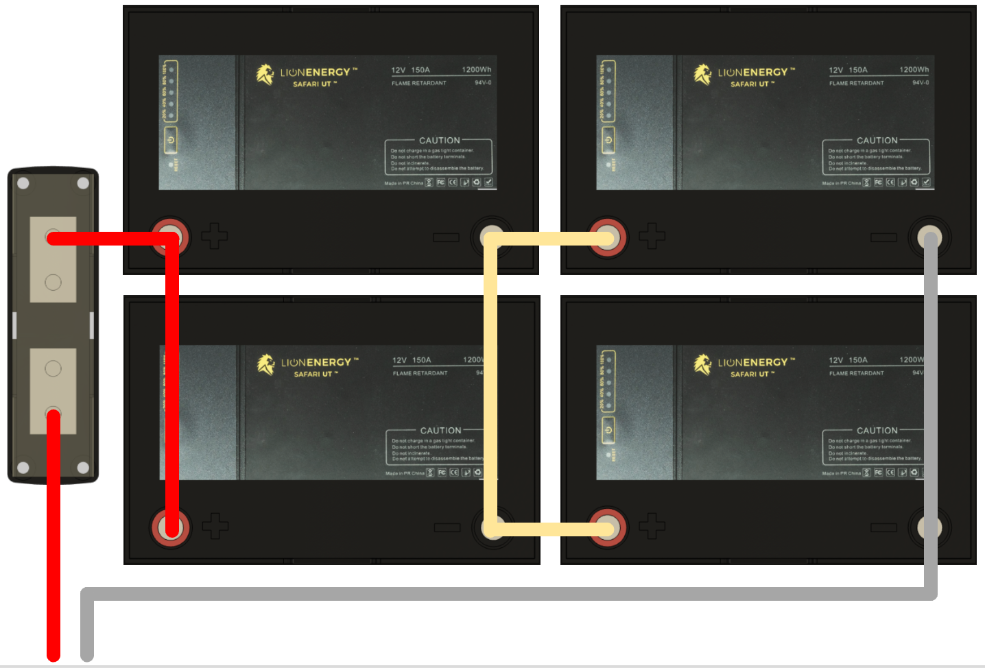
According to the Wiring Unlimited document, this approach requires midpoint monitoring to detect deviations in voltage between the upper and lower batteries. In addition, when deviations are detected and reported, they must be acted on to deal with potential issues. Batteries in the battery bank may be damaged if reported problems are not resolved. Monitoring the midpoint has the advantage of detecting these issues that might otherwise go unnoticed. The Victron SmartShunt, which we intend to use in our system, can monitor midpoint voltages and raise alarms when problems arise.
12 Volt Battery Bank
Alternatively, four UT 1200 batteries can be connected in parallel to yield a 12 V battery bank, delivering the same 4,608 Wh. This configuration also adds more redundancy in case a battery fails while in the field. The obvious configuration to accomplish this is shown in Figure 3.
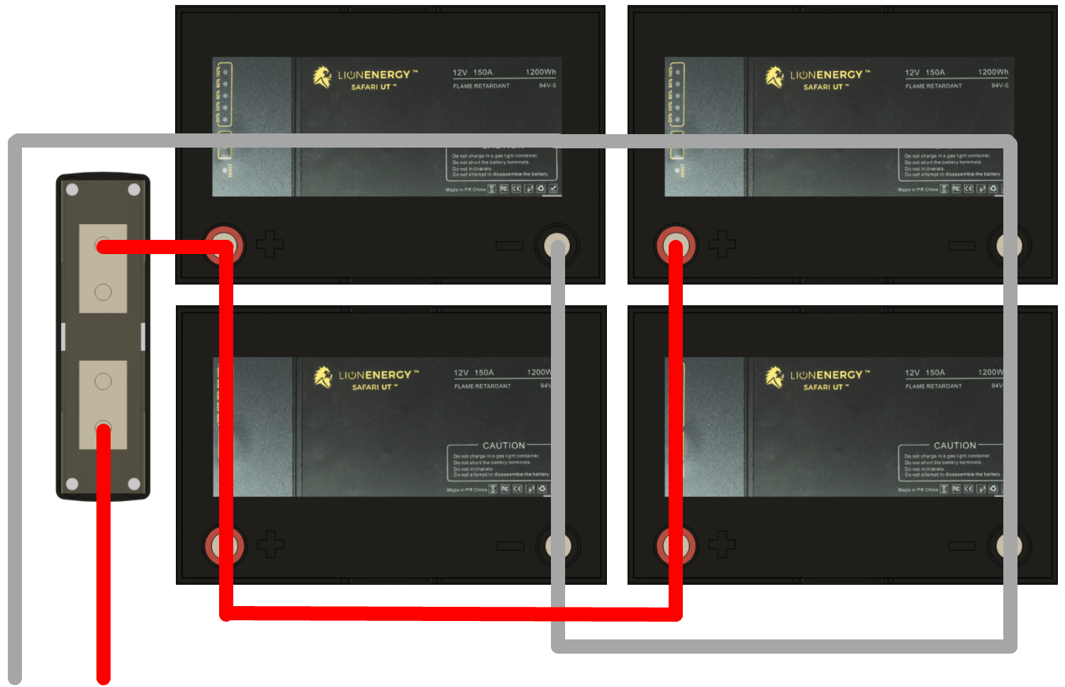
Notice in Figure 3 that the positive connection comes from the upper left battery in the bank, and the negative connection comes from the upper right or the last battery in the bank.
In a 12 V system, the currents are double those of a 24 V system. These higher currents demand a 400 A Class T fuse and wire with double the cross-sectional area of wire used in a similar 24 V system.
A cleaner wiring layout that still respects the principle of keeping circuit lengths equivalent is illustrated in Figure 4.
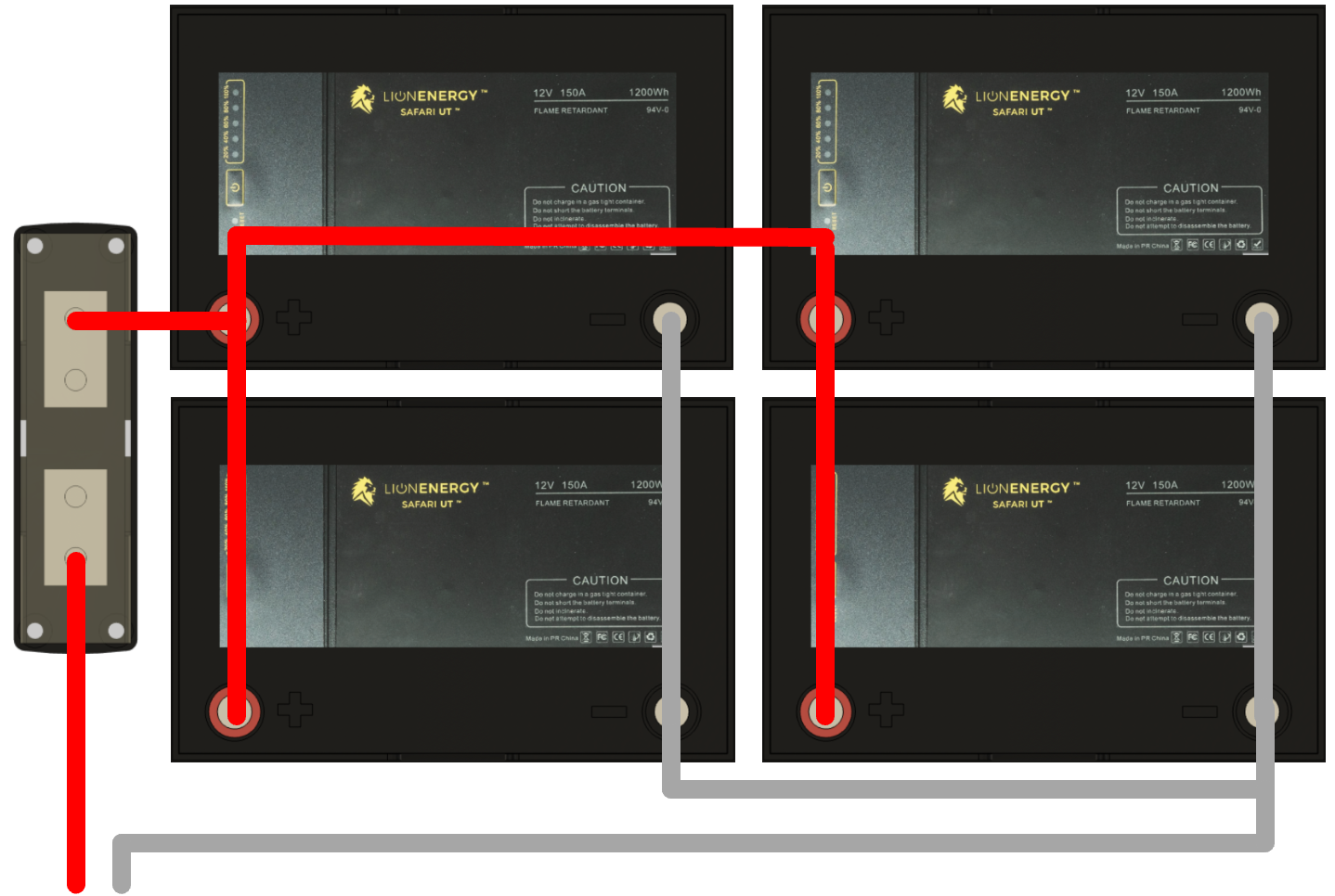
In the hopes of reducing system currents, voltage drops, and associated ripple, we desire to create a 24 V system. However, if this is impossible due to the lack of availability of an appropriate inverter/charger, the 12 V layout, illustrated in Figure 4, will be used.
Battery Bank Placement
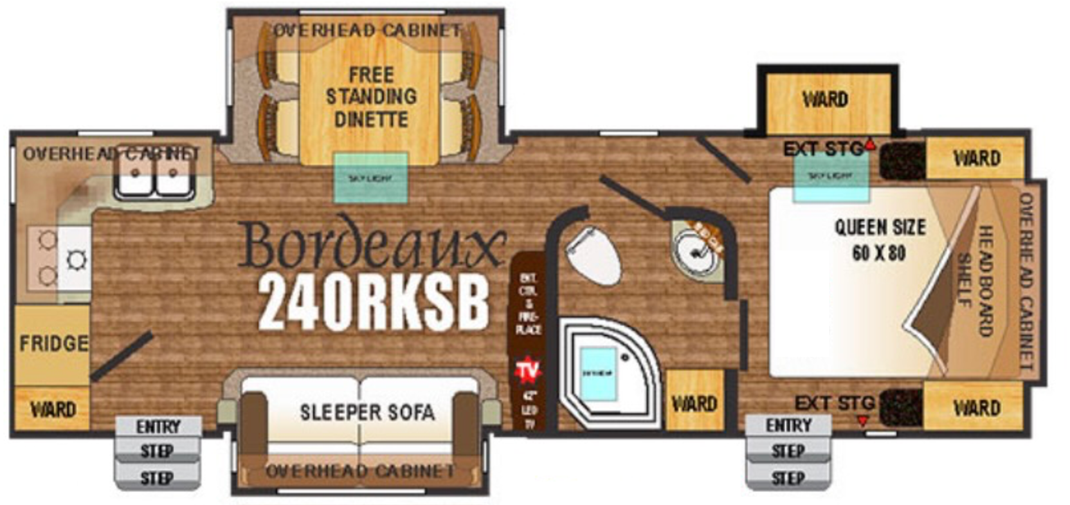
Our RV is a 2016 Outdoor RV Blackstone 240 RKSB. The floorplan of this model is illustrated in Figure 5. Our new Power Center will be located in the left-hand side of the pass-through storage area that is accessed by an exterior door located in the upper right-hand corner of Figure 5. Batteries should be located as close as possible to their associated invert/charger to reduce voltage drops that may occur over long cables. To keep the cables short but still leave storage areas available for their intended purpose, our battery bank will be located under the foot of the bed.
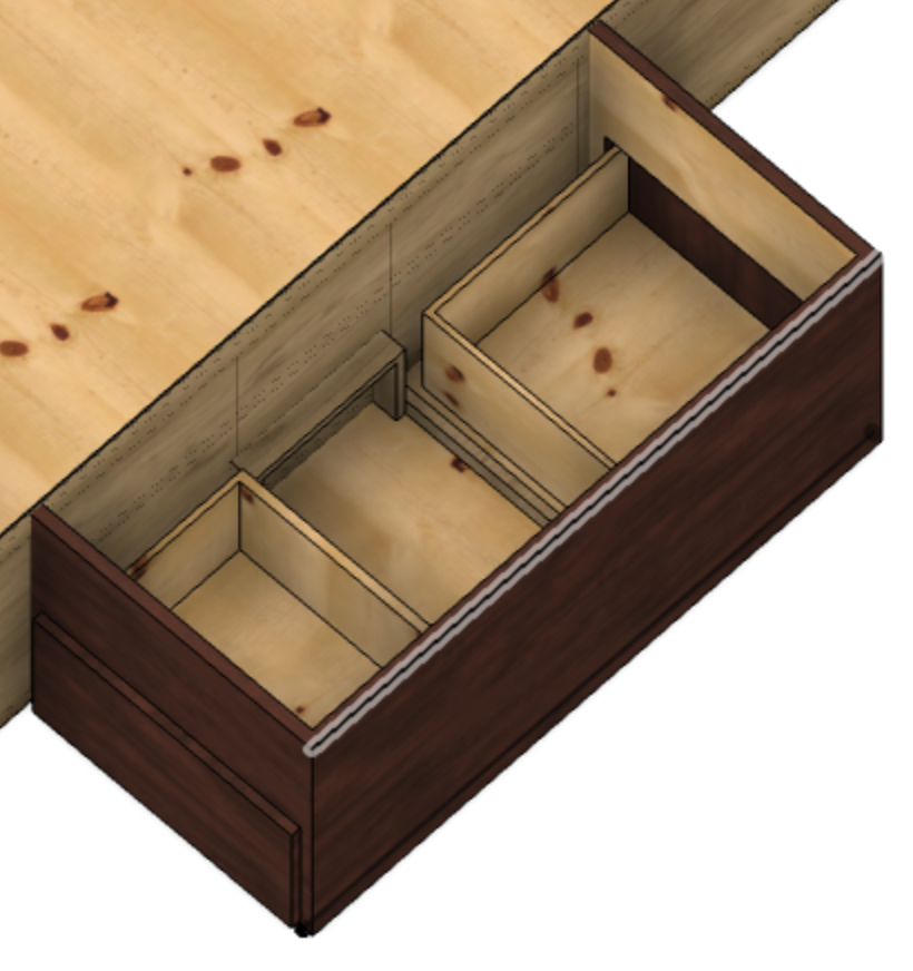
In our last post, we determined that space between the drawers was available for our battery bank. This open space was found during our modeling efforts and is illustrated in Figure 6.
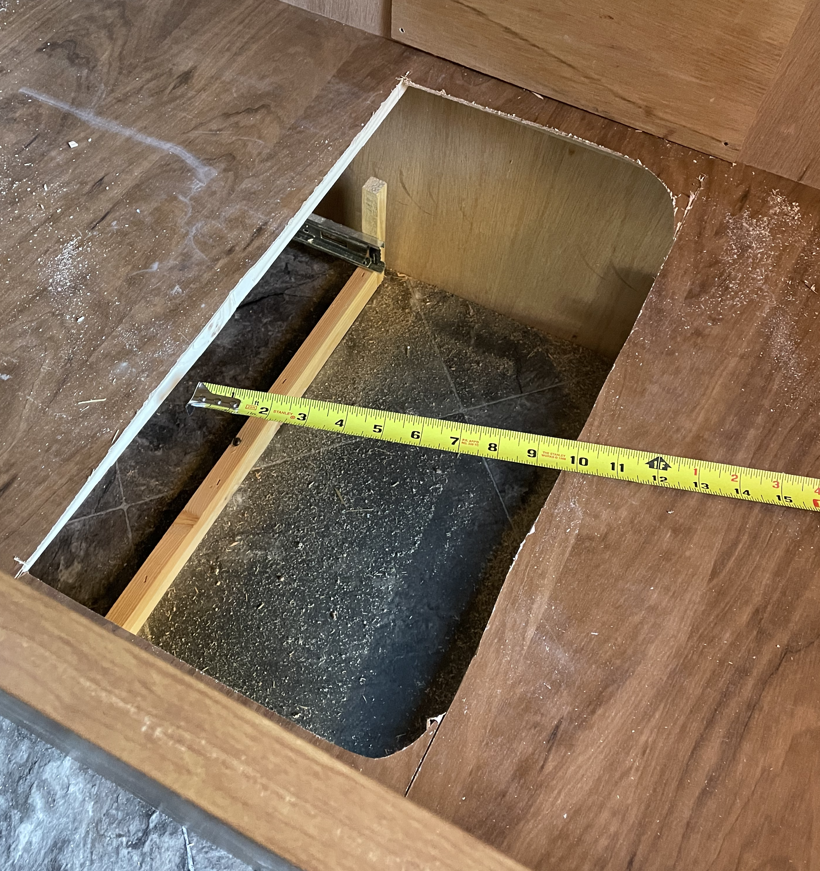
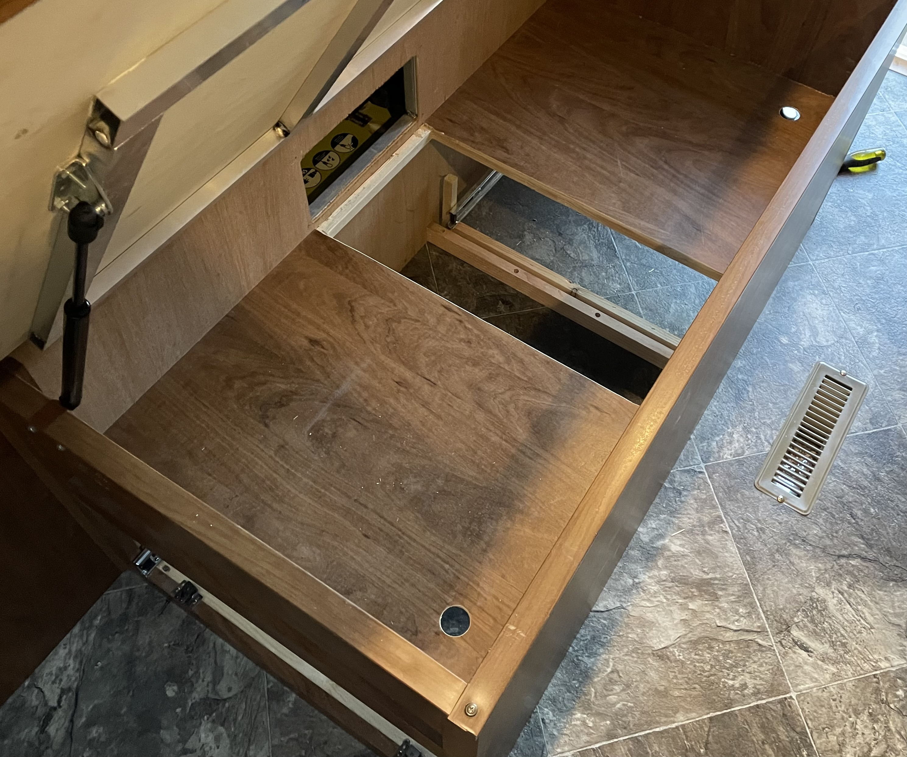
The UT 1200 batteries measure 10.2″ long, 8.8″ tall, and 6.6″ wide. We started demolition to determine the best way to orient these batteries within the available space. We knew from our previous inspections that two cross beams were holding up the false floor of the storage area above the drawers. We removed the drawers and, using a jigsaw, removed the portion of the false floor between the beams. This roughed-out hole and the exposed space are shown in Figure 7.
While the drawers are only 17″ from front to back, the glides they’re on are 18″ long. The distance between the backs of one set of glides and the other is insufficient for two side-by-side batteries to sit between them. Unfortunately, 17″ drawer glides are unavailable, and the next size down is 16″.
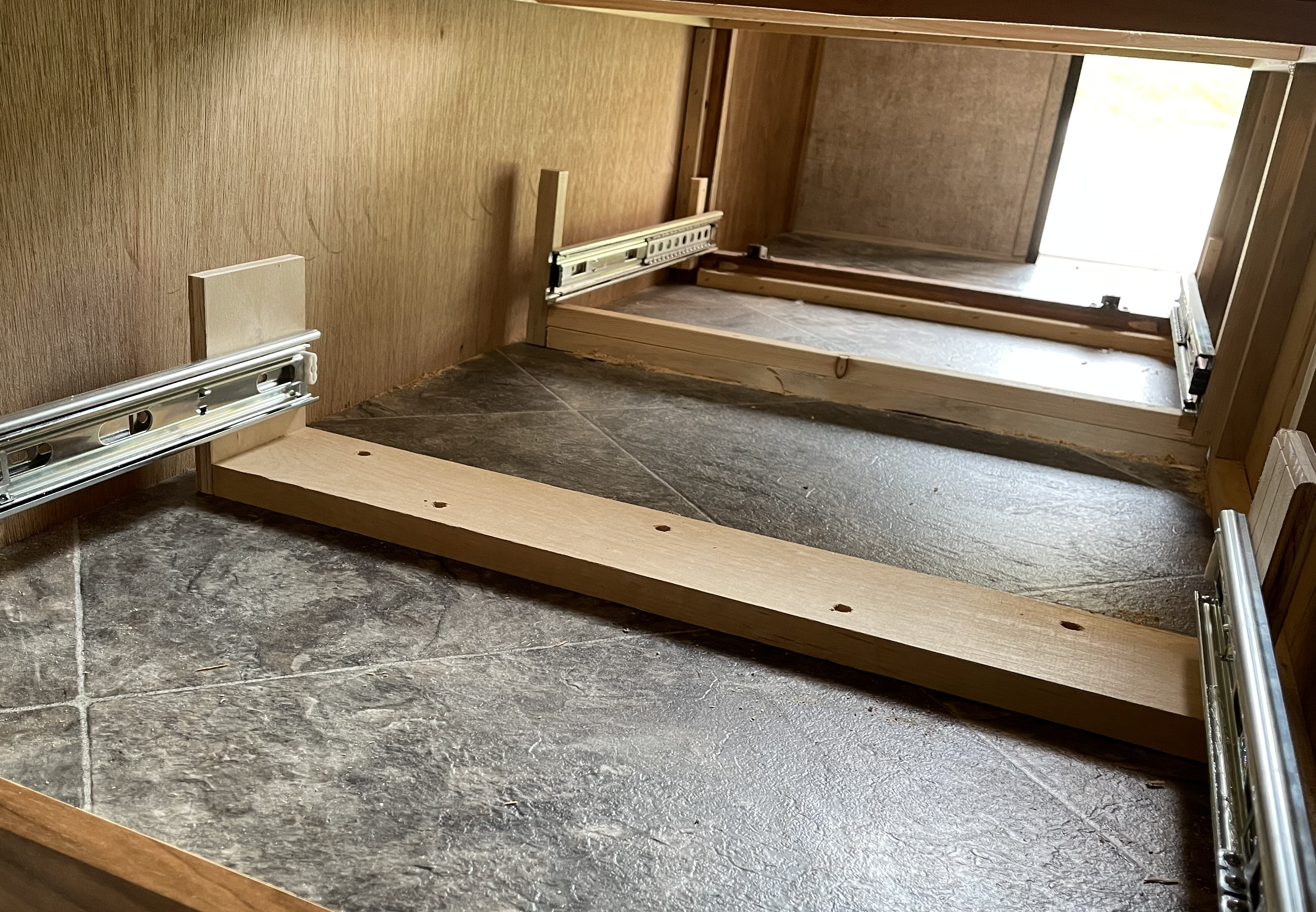
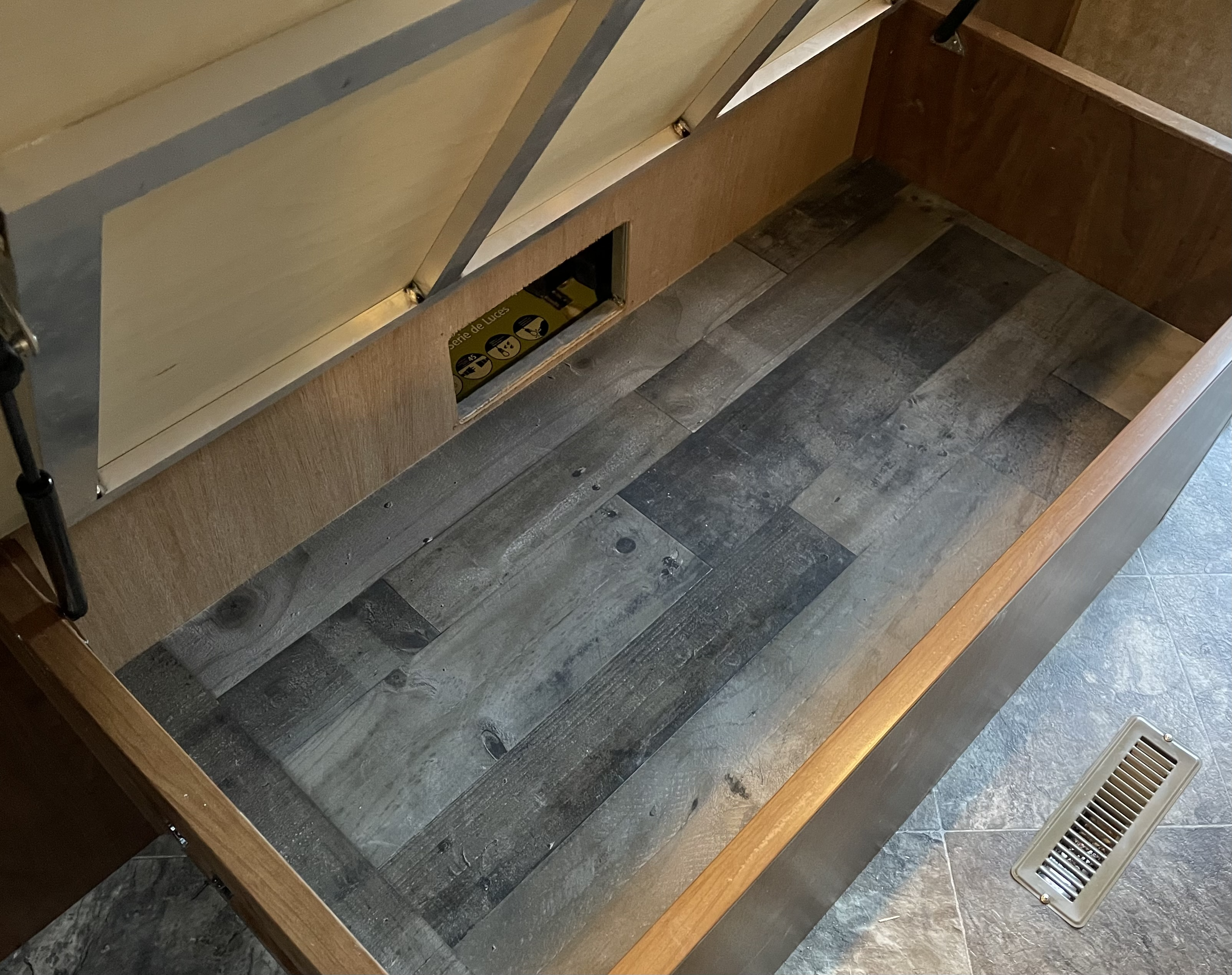
The lack of space necessitated converting one of our drawers to 16″ glides and adjusting the drawer to match. After removing the glide supports and drawer glides, we constructed a new and more robust support structure shown in Figure 8.
We acquired and installed new 16″ drawer glides. In addition, we disassembled the associated drawer, cut 1″ off the sides and bottom, and reassembled it better than new.
The remaining space between the backs of both drawers is now more than sufficient to hold two UT 1200’s side by side. The distance from right to left in Figure 8 is also more than enough to hold two UT 1200s longwise. There is also enough space for the fuse holder that needs to be located near the battery bank.
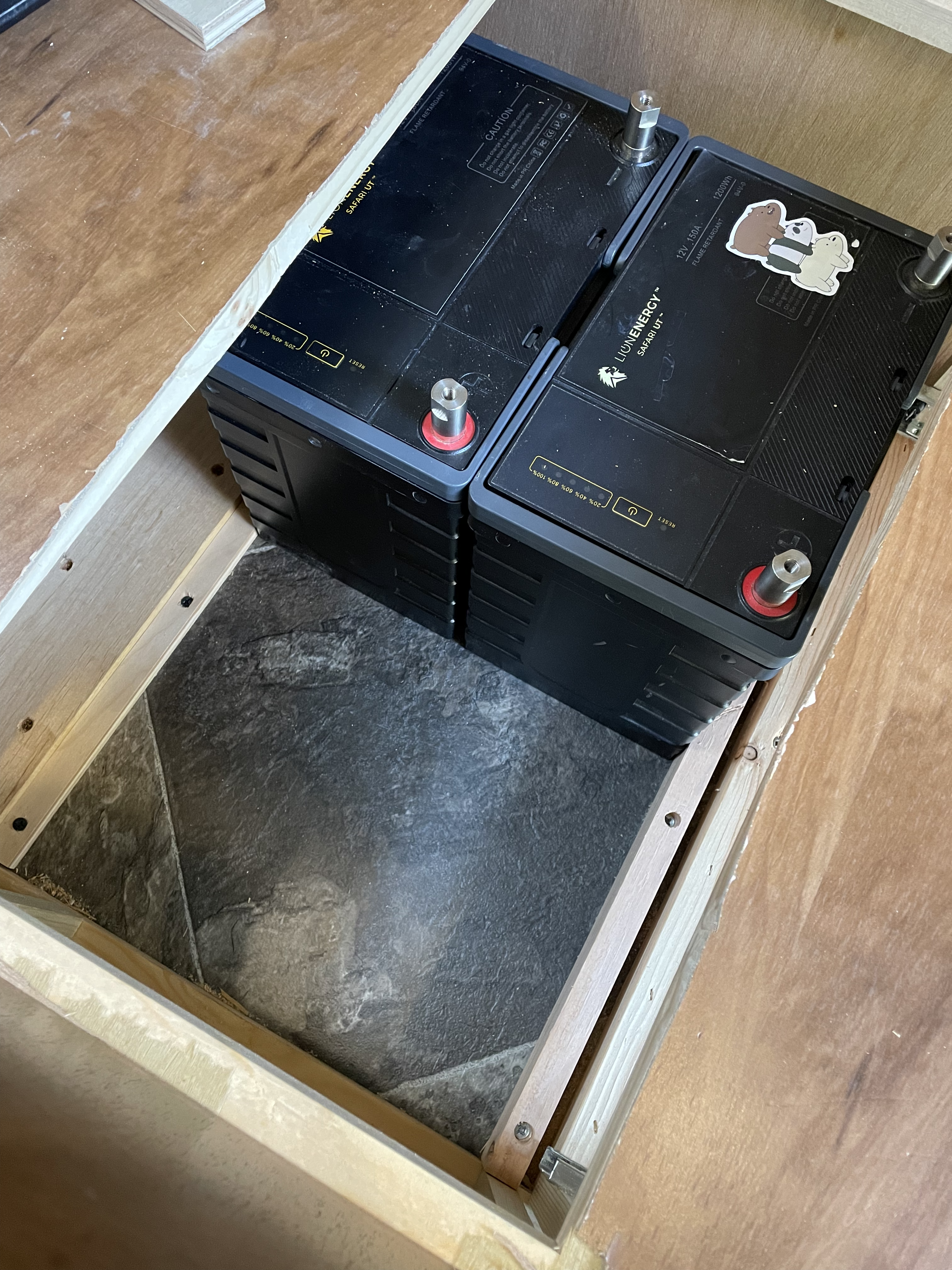
To assist in holding the batteries firmly in place, we added two cleats to the floor spaced to allow the batteries to sit side by side with little to no room to spare. The cleats and batteries can be seen in Figure 9. Also, notice in Figure 9 that the roughed-out access hole has been cleaned up using a round-over bit in our router, some chisel work, and a bit of sanding.
To restore the utility of the storage space used to provide access to the batteries, we drilled finger holes in the remaining false floor. We also added another false bottom over the top of what can be seen in Figure 9. This can be seen in Figures 10 and 11.
The End Result
In the spirit of making incremental progress and leaving the trailer functional for camping, we’ve reached the end of this sub-project. We successfully created an excellent space for our battery bank that will work for either a 24 V or a 12 V system. The only negative impact of this sub-project was one drawer is now an inch shorter. In future posts, we’ll install the batteries, wire them together, create a small shelf for the fuse holder, and wire the battery bank to the battery disconnect switch and the SmartShunt.