
This post is the sixth of an ongoing series of articles documenting and describing our RV electrical upgrade. Our previous post in this series described the Victron Energy Lynx Distributor and a minor modification we made to it to meet our needs better. This post describes the original shore power wiring and our improvements. In addition, we discuss a severe flaw that was difficult to find.
Shore Power
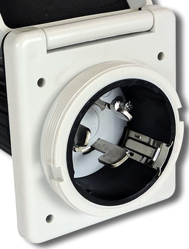
Figure 1 illustrates a typical 50 A RV shore power connector. A power cord may connect this outlet to a shore power pedestal that provides 50 A AC power to run appliances such as air conditioners, microwaves, televisions, and power converters for charging batteries. In addition, a 50 A connector can be adapted to a 30 A or 15 A power source using appropriate converters or dogbones. Alternatively, this connector may be connected to a generator when shore power is unavailable.
The connector illustrated in Figure 1 connects to the RV circuit breaker panel via appropriate conductors inside the RV. For example, our Outdoor RV 240 RKSB has 6/3 Romex that connects the shore power outlet to the main breaker in the circuit breaker panel, as illustrated in Figure 2.
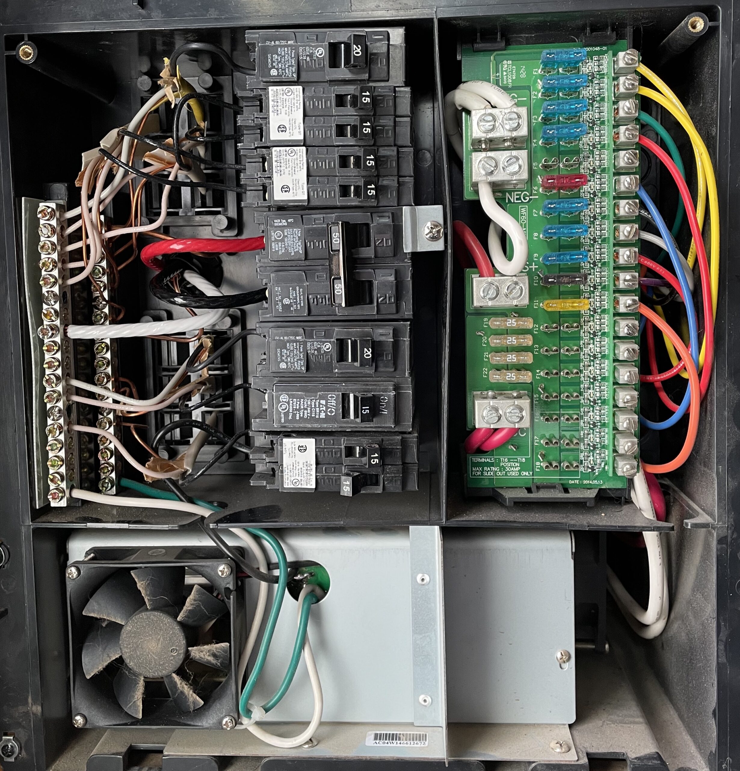
6/3 Romex has three 6 AWG conductors and one 10 AWG bare copper wire. The 6 AWG red and black wires are connected to the 50 A breaker. The white wire is the associated neutral wire connected to the neutral busbar. The bare copper wire is attached directly to the ground busbar.
The left side of the circuit breaker panel distributes 120 V AC to various trailer components, including 120 V AC outlets, television, microwave, air conditioner, and the power converter located beneath the circuit breaker panel, as illustrated in Figure 2. The power converter converts 120 V AC into the appropriate DC voltages to charge our 12 V RV batteries.
The right side of the circuit breaker panel acquires power from the 12 V RV batteries and distributes this through blade fuses to various RV components such as lights, pull-outs, pumps, USB ports, audio systems, etc. In addition, the power converter output connects to the batteries via this side of the panel for charging.
Inverter/Charger Power
The ability to use all of our 120 V appliances without needing shore power or a generator is the primary objective of this project. Including an inverter/charger in our power center will accomplish this goal. The desired inverter charger will pass through shore or generator power when available and provide 120 V power when they are not. The inverter/charger requires shore power as an input, and its 120 V AC output must be connected to the circuit breaker panel to enable this feature.
We desired to leave the shore power outlet in its original location, requiring us to run 6/3 Romex from the shore power connector to our new power center and another strand of 6/3 Romex from our power center to the circuit breaker panel. Rather than running these two strands to two different locations, we determined to run both from our power center to just behind the circuit breaker panel.
Rather than fussing with the RV underlayment, routing the cables around tanks, and through the frame, we hired this out to Stewart’s RV, our local RV service center. We purchased 125 feet of cable and delivered it to the service folks at Stewart’s, who did an excellent job in all but one aspect. We’ll address the one flaw in the next section.
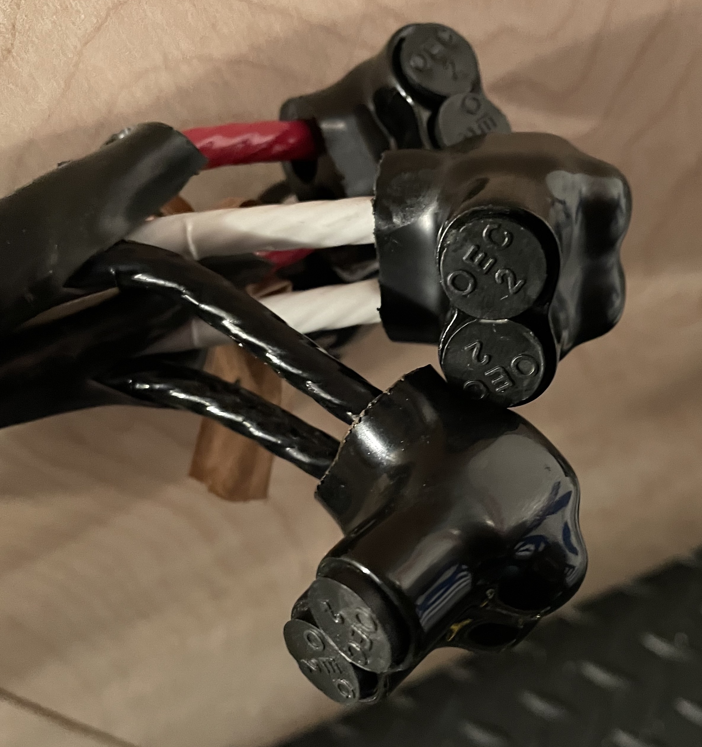
Once the wiring was in place, we made the right connections. First, we detached the original shore power connection from the circuit breaker panel and spliced it to one of the new 6/3 Romex strands using four two-conductor Morris connectors. These connections are illustrated in Figure 3. Next, we combined the two strands of 6/3 Romex in our power center using four additional Morris connectors. Finally, we joined the remaining conductors to the circuit breaker panel. With these modifications, shore or generator power comes in through the shore power connection, over the original 6/3 wire, through a new strand of 6/3 Romex to our power center, back through the second strand of 6/3 Romex, arriving at the circuit breaker panel. The before and after connections are identical, but the path has increased by roughly 50 feet.
The spliced 6/3 Romex cables in our power center will be separated when our inverter/charger is installed. The 6/3 cable coming from the shore power connector will be tied to the inverter/charger’s input. The remaining cable will be connected to the inverter/charger’s 120 V AC output.
Testing, Debugging, Repairing
Before connecting shore or generator power to our RV, I tested for short circuits within the circuit breaker panel. Unfortunately, I found a low resistance short circuit between the ground and neutral busbar. As a sub-panel, this should not be the case. I looked for obvious wiring flaws but didn’t find any. I returned our trailer to the service center, reporting a short circuit between ground and neutral.
They made a thorough inspection of their work and found no flaws. They did what I should have done after installing the wires and before wiring things together. They tested the continuity between each possible conductor pair of both strands and found no short circuits. I accepted their findings and began a tedious search for the truth. I completely rewired the circuit breaker panel and eventually convinced myself that perhaps it was a strange interaction with the power converter, etc.
I determined to plug the trailer in and see what happens. I knew it wouldn’t be a disaster, but I wanted to see if it would work. Unfortunately, immediately after plugging in the trailer, the GFCI outlet tripped. After much more work, I determined to plug it into a non GFCI protected outlet, and the trailer worked great. I carefully measured the potential between the trailer frame and ground to ensure my safety; everything was fine, well, it seemed fine.
GFCI outlets trip because the current on the hot wires differs from that of the neutral wire by more than 5 mA. In other words, GFCI trips when current is flowing through some undesirable path, like through you. So why was this happening? A considerable amount of literature describes GFCI failures due to long runs, over 100 feet, for example. Essentially, the longer the wire, the more leakage between conductors, and when this exceeds 5 mA, the GFCI trips. Therefore, the longer the wire, the more likely this is. While I had successfully used the failing shore power connection previously, I also recognized that I recently added nearly 50′ to the circuit through my new wiring. Perhaps this was the culprit. I moved the trailer much closer to the outlet and removed more than 50′ of cords, and it still failed.
After disconnecting the cable from the circuit breaker panel and removing the Morris connectors, I rechecked each conductor to ensure independence. Still no short circuits detected. Finally, in a last-ditch effort to find the flaw, I checked each wire in each cable for connectivity to the trailer’s frame. I found the elusive, obvious, and now embarrassing culprit. When the service center installed one of the new cables, its neutral wire was inadvertently electrically connected to the trailer’s frame.
The circuit fails as follows. The ground busbar in the circuit breaker panel is appropriately attached to the trailer’s frame. However, when the faulty neutral wire is connected to the neutral busbar, the trailer’s frame connects the neutral and ground busbars, which is inappropriate for a subpanel.
The test for this condition is simple and easily recreated. I returned the trailer to Stewart’s RV, demonstrated the test described above to them, and they accepted responsibility for the issue. They removed each cable clamp assembly installed, inspected for damage, and repaired where the wire insulation was cut and shorted the neutral wire to the frame. They demonstrated great integrity and excellent service through this ordeal and were consistently friendly and polite. They will get all of my future business.
Summary
Our new AC wiring is in place and works perfectly. One of our goals was to end each sub-project with our trailer in order and available for camping. With this project done and working, we’ve reached that goal. Several takeaways:
- Morris connectors are amazingly awesome and much easier to work with than junction boxes.
- Vendors, such as Stwart’s RV, with integrity are a pleasure to work with even when things seem tough.
- Most importantly, check continuity between each conductor and between each conductor and the trailer’s frame! This one simple test would have saved dozens of hours of searching, poking, disconnecting, etc.
This project was our least understood because of the difficulty and uncertainty of physically dragging cable from the very front to the very back of our RV. However, the rest should be easy with this step done and working. Did I say that out loud?